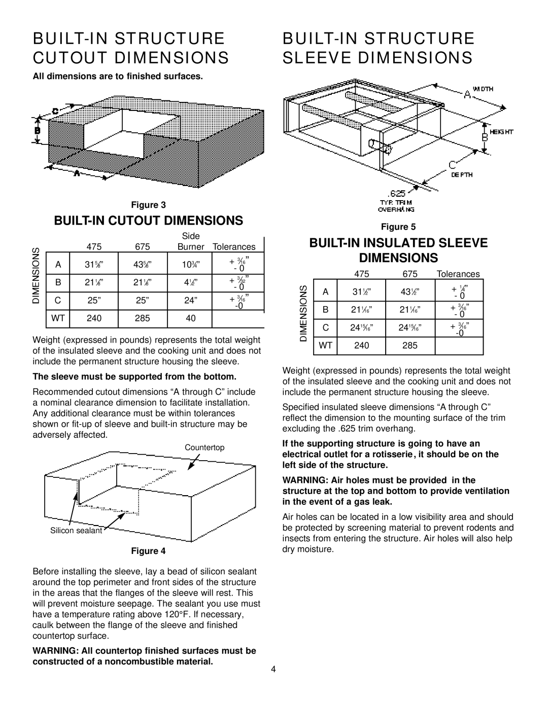
BUILT-IN STRUCTURE CUTOUT DIMENSIONS
All dimensions are to finished surfaces.
Figure 3
BUILT-IN CUTOUT DIMENSIONS
|
|
| Side |
|
| 475 | 675 | Burner | Tolerances |
A | 315⁄8” | 435⁄8” | 103⁄4” | + 3⁄16” |
|
|
|
| - 0 |
B | 211⁄8” | 211⁄8” | 41⁄2” | + 3⁄32” |
|
|
|
| - 0 |
C | 25” | 25” | 24” | + 3⁄16” |
|
|
|
| |
WT | 240 | 285 | 40 |
|
Weight (expressed in pounds) represents the total weight of the insulated sleeve and the cooking unit and does not include the permanent structure housing the sleeve.
The sleeve must be supported from the bottom.
Recommended cutout dimensions “Athrough C” include a nominal clearance dimension to facilitate installation. Any additional clearance must be within tolerances shown or
Countertop
Silicon sealant ![]()
Figure 4
Before installing the sleeve, lay a bead of silicon sealant around the top perimeter and front sides of the structure in the areas that the flanges of the sleeve will rest. This will prevent moisture seepage. The sealant you use must have a temperature rating above 120°F. If necessary, caulk between the flange of the sleeve and finished countertop surface.
WARNING: All countertop finished surfaces must be constructed of a noncombustible material.
BUILT-IN STRUCTURE SLEEVE DIMENSIONS
Figure 5
BUILT-IN INSULATED SLEEVE
DIMENSIONS
| 475 | 675 | Tolerances |
A | 311⁄2” | 431⁄2” | + 1⁄4” |
|
|
| - 0 |
B | 1 | 1 | + 3⁄16” |
21 ⁄16” | 21 ⁄16” | - 0 | |
|
|
| |
C | 2415⁄16” | 2415⁄16” | + 3⁄16” |
|
|
| |
WT | 240 | 285 |
|
Weight (expressed in pounds) represents the total weight of the insulated sleeve and the cooking unit and does not include the permanent structure housing the sleeve.
Specified insulated sleeve dimensions “Athrough C” reflect the dimension to the mounting surface of the trim excluding the .625 trim overhang.
If the supporting structure is going to have an electrical outlet for a rotisserie, it should be on the left side of the structure.
WARNING: Air holes must be provided in the structure at the top and bottom to provide ventilation in the event of a gas leak.
Air holes can be located in a low visibility area and should be protected by screening material to prevent rodents and insects from entering the structure. Air holes will also help dry moisture.
4