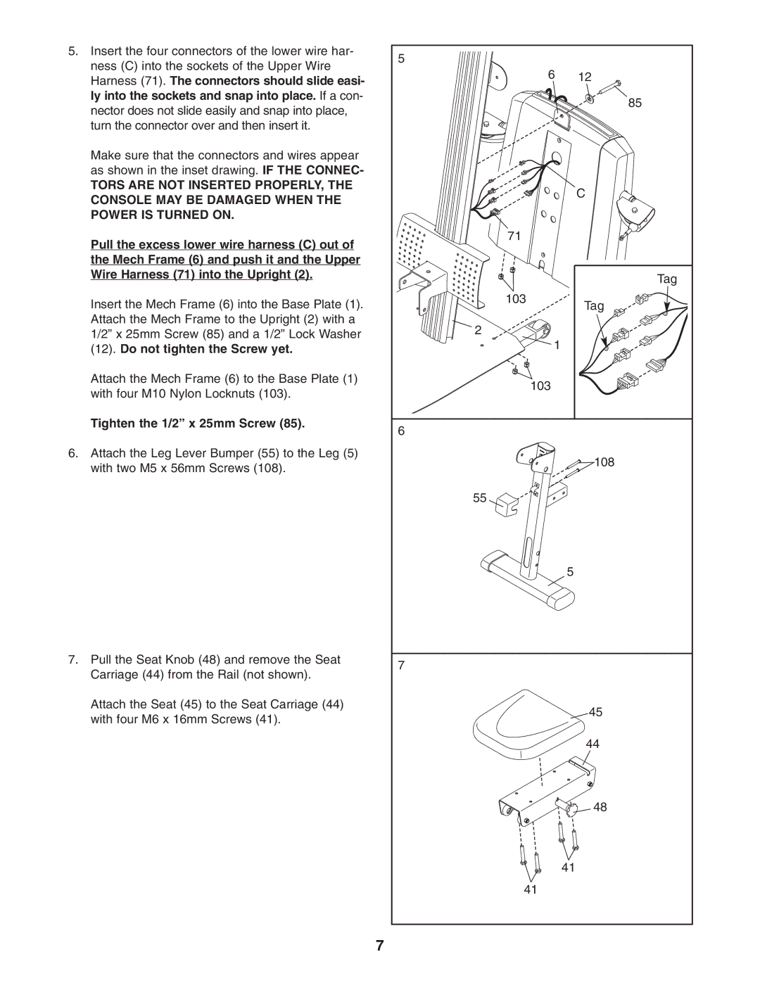
5.Insert the four connectors of the lower wire har- ness (C) into the sockets of the Upper Wire Harness (71). The connectors should slide easi- ly into the sockets and snap into place. If a con- nector does not slide easily and snap into place, turn the connector over and then insert it.
Make sure that the connectors and wires appear as shown in the inset drawing. IF THE CONNEC-
TORS ARE NOT INSERTED PROPERLY, THE CONSOLE MAY BE DAMAGED WHEN THE POWER IS TURNED ON.
Pull the excess lower wire harness (C) out of the Mech Frame (6) and push it and the Upper Wire Harness (71) into the Upright (2).
Insert the Mech Frame (6) into the Base Plate (1). Attach the Mech Frame to the Upright (2) with a 1/2” x 25mm Screw (85) and a 1/2” Lock Washer (12). Do not tighten the Screw yet.
Attach the Mech Frame (6) to the Base Plate (1) with four M10 Nylon Locknuts (103).
Tighten the 1/2” x 25mm Screw (85).
6.Attach the Leg Lever Bumper (55) to the Leg (5) with two M5 x 56mm Screws (108).
7.Pull the Seat Knob (48) and remove the Seat Carriage (44) from the Rail (not shown).
Attach the Seat (45) to the Seat Carriage (44) with four M6 x 16mm Screws (41).
5 |
|
6 | 12 |
| 85 |
| C |
71 |
|
| Tag |
103 | Tag |
| |
2 |
|
1 |
|
103 |
|
6 |
|
| 108 |
55 |
|
| 5 |
7 |
|
| 45 |
| 44 |
| 48 |
| 41 |
41 |
|
7