49.Make sure that all parts have been properly tightened before using the weight system. The use of the remaining parts will be explained in ADJUSTMENTS, beginning below.
Before using the weight system, pull each cable a few times to make sure that the cables move smoothly over the pulleys. If one of the cables does not move smoothly, find and correct the problem. IMPORTANT: If the cables are not properly installed, they may be damaged when heavy weight is used. See the CABLE DIAGRAMS on page 23 of this manual for proper cable routing. If there is any slack in the cables, you will need to remove the slack by tightening the cables. See
ADJUSTMENTS
The instructions below describe how each part of the weight system can be adjusted. Refer to the exercise guide accompanying this manual to see how the weight system should be set up for each exercise. IMPOR-
TANT: When attaching the lat bar or nylon strap, make sure that the attachments are in the correct start- ing position for the exercise to be performed. If there is any slack in the cables or chain as an exercise is performed, the effectiveness of the exercise will be reduced.
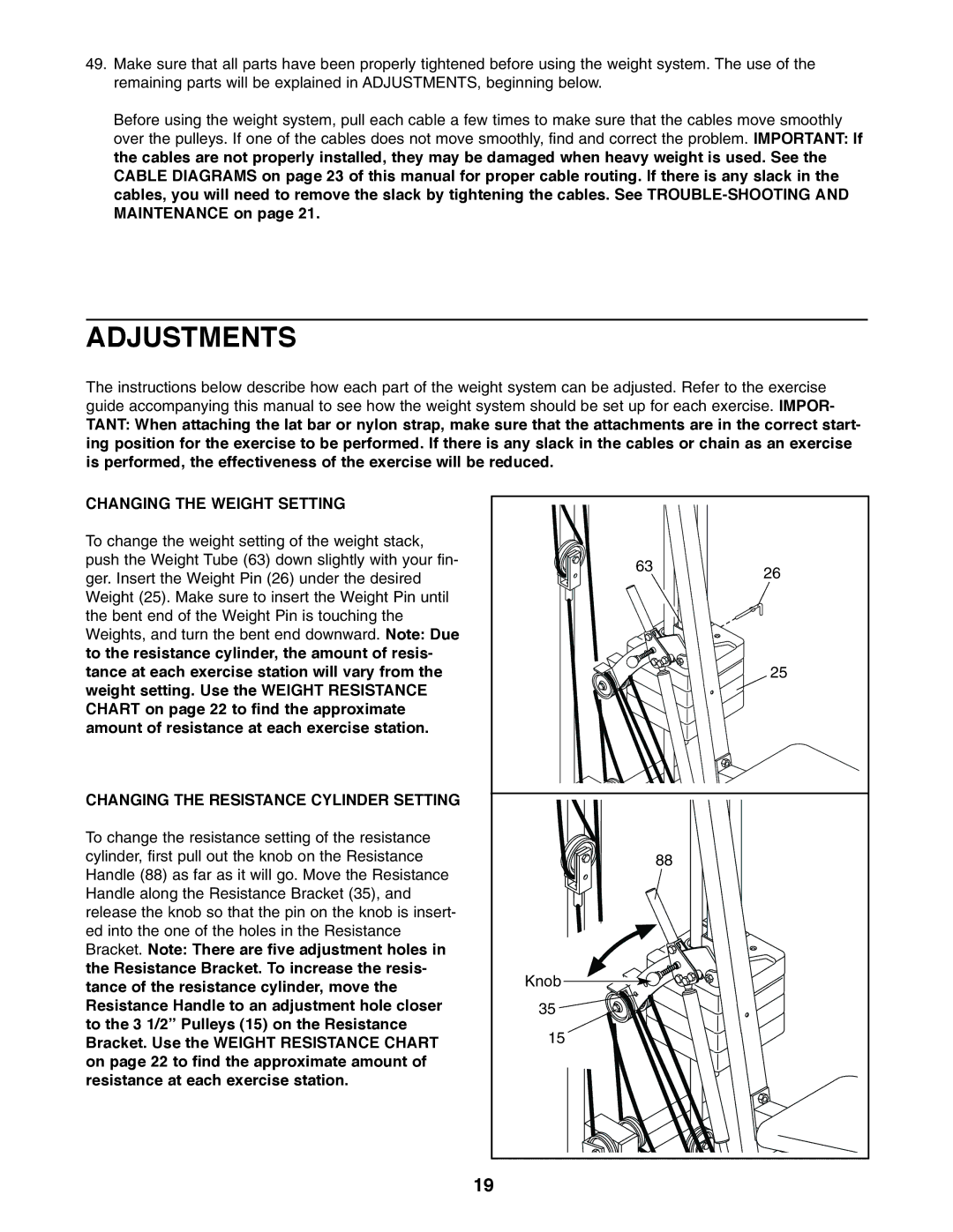
CHANGING THE WEIGHT SETTING
To change the weight setting of the weight stack, push the Weight Tube (63) down slightly with your fin- ger. Insert the Weight Pin (26) under the desired Weight (25). Make sure to insert the Weight Pin until the bent end of the Weight Pin is touching the Weights, and turn the bent end downward. Note: Due to the resistance cylinder, the amount of resis- tance at each exercise station will vary from the weight setting. Use the WEIGHT RESISTANCE CHART on page 22 to find the approximate amount of resistance at each exercise station.
CHANGING THE RESISTANCE CYLINDER SETTING
To change the resistance setting of the resistance cylinder, first pull out the knob on the Resistance Handle (88) as far as it will go. Move the Resistance Handle along the Resistance Bracket (35), and release the knob so that the pin on the knob is insert- ed into the one of the holes in the Resistance Bracket. Note: There are five adjustment holes in the Resistance Bracket. To increase the resis- tance of the resistance cylinder, move the Resistance Handle to an adjustment hole closer to the 3 1/2” Pulleys (15) on the Resistance Bracket. Use the WEIGHT RESISTANCE CHART on page 22 to find the approximate amount of resistance at each exercise station.
63 | 26 |
| |
| 25 |
| 88 |
Knob |
|
35 |
|
15 |
|
19 |
|