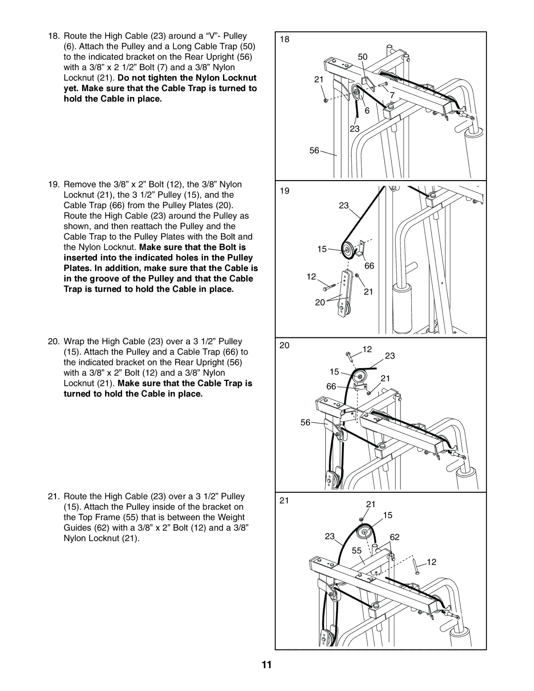
18.Route the High Cable (23) around a “V”- Pulley
(6). Attach the Pulley and a Long Cable Trap (50) to the indicated bracket on the Rear Upright (56) with a 3/8” x 2 1/2” Bolt (7) and a 3/8” Nylon Locknut (21). Do not tighten the Nylon Locknut yet. Make sure that the Cable Trap is turned to hold the Cable in place.
19.Remove the 3/8” x 2” Bolt (12), the 3/8” Nylon Locknut (21), the 3 1/2” Pulley (15), and the Cable Trap (66) from the Pulley Plates (20). Route the High Cable (23) around the Pulley as shown, and then reattach the Pulley and the Cable Trap to the Pulley Plates with the Bolt and the Nylon Locknut. Make sure that the Bolt is inserted into the indicated holes in the Pulley Plates. In addition, make sure that the Cable is in the groove of the Pulley and that the Cable Trap is turned to hold the Cable in place.
20.Wrap the High Cable (23) over a 3 1/2” Pulley (15). Attach the Pulley and a Cable Trap (66) to the indicated bracket on the Rear Upright (56) with a 3/8” x 2” Bolt (12) and a 3/8” Nylon Locknut (21). Make sure that the Cable Trap is turned to hold the Cable in place.
21.Route the High Cable (23) over a 3 1/2” Pulley (15). Attach the Pulley inside of the bracket on the Top Frame (55) that is between the Weight Guides (62) with a 3/8” x 2” Bolt (12) and a 3/8” Nylon Locknut (21).
18 |
| |
| 50 | |
21 |
| |
| 7 | |
| 6 | |
| 23 | |
56 |
| |
19 |
| |
| 23 | |
15 |
| |
| 66 | |
12 |
| |
| 21 | |
20 |
| |
20 | 12 | |
| ||
| 23 | |
15 | 21 | |
66 | ||
| ||
56 |
| |
21 | 21 | |
| ||
| 15 | |
23 | 62 | |
| 55 | |
| 12 |
11
