3![]()
![]()
![]()
Install water piping (continued)
Sizing DHW system piping
When using the boiler for dedicated DHW applications, use the circulator supplied with the boiler (007 for
1.Figure 5 shows recommended DHW piping, as shown in Figures 7 through 10, pages 15 – 18. All show direct connection of the DHW piping to the boiler because the boiler circulator shuts down during DHW operation.
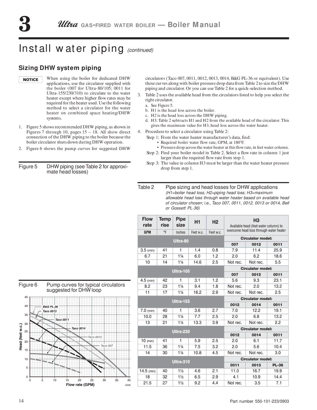
2.Figure 6 shows the pump curves for suggested DHW
Figure 5 DHW piping (see Table 2 for approxi- mate head losses)
circulators (Taco 007, 0011, 0012, 0013, 0014, B&G
3.Table 2 uses the available head from the circulators listed to help you select the right circulator.
a.See Figure 5.
b.H1 is the head loss across the boiler.
c.H2 is the head loss across the DHW piping.
d.H3: Table 2 subtracts H1 and H2 from the available head of the circulator. This gives the maximum value for H3, head loss across the water heater.
4.Procedure to select a circulator using Table 2:
Step 1: From the water heater manufacturer’s data, find:
•Required boiler water flow rate, GPM, at 180°F.
•Pressure drop across the water heater at this flow rate, in feet water column. Step 2: Find your boiler model in Table 2. Select a flow rate in column 1 just
larger than the required flow rate from step 1.
Step 3: The value in column H3 must be larger than the water heater pressure drop from step 1.
Figure 6 Pump curves for typical circulators suggested for DHW loop
14
Table 2 Pipe sizing and head losses for DHW applications
(H1=boiler head loss; H2=piping head loss; H3=maximum allowable head loss through water heater based on available head of circulator chosen; i.e., Taco 007, 0011, 0012, 0013 or 0014, Bell or Gossett
Part number |