PFG Series 7
Size and install gas piping
In sizing the gas piping, the following factors should be considered.
a)Diameter and length of the gas supply piping.
b)Number of fittings.
c)Maximum gas consumption (including any pos- sible future expansion).
d)Allowable loss in gas pressure from gas meter out- let to boiler. For pressure drops, see ANSI
1.Size natural gas piping from the following table. Piping must be sized to provide proper inlet gas pressure to the gas valve when boiler is operating at rated input. For natural gas, inlet gas pressure to gas valve should be a minimum of 5 inches water column and a maximum of 13 inches water column. If inlet natural gas pressure exceeds 13 inches water column, a 100 percent
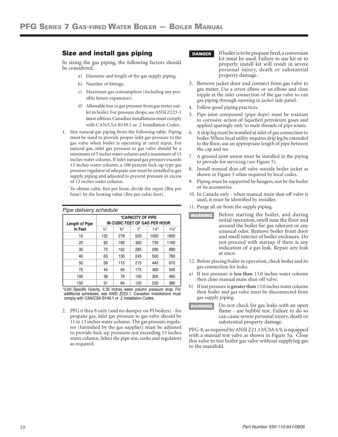
To obtain cubic feet per hour, divide the input (Btu per hour) by the heating value (Btu per cubic foot).
Pipe delivery schedule
2.PFG 6 thru 8 only (and no damper on PI boilers) - for propane gas, inlet gas pressure to gas valve should be 11 to 13 inches water column. The gas pressure regula- tor (furnished by the gas supplier) must be adjusted to provide
If boiler is to be propane fired, a conversion kit must be used. Failure to use kit or to properly install kit will result in severe personal injury, death or substantial property damage.
3.Remove jacket door and connect from gas valve to gas meter. Use a street elbow or an elbow and close nipple at the inlet connection of the gas valve to run gas piping through opening in jacket side panel.
4.Follow good piping practices.
5.Pipe joint compound (pipe dope) must be resistant to corrosive action of liquefied petroleum gases and applied sparingly only to male threads of pipe joints.
6.A drip leg must be installed at inlet of gas connection to boiler. Where local utility requires drip leg be extended to the floor, use an appropriate length of pipe between the cap and tee.
7.A ground joint union must be installed in the piping to provide for servicing (see Figure 5).
8.Install manual
9.Piping must be supported by hangers, not by the boiler or its accessories.
10.In Canada only - when manual main shut off valve is used, it must be identified by installer.
11.Purge all air from the supply piping.
Before starting the boiler, and during initial operation, smell near the floor and around the boiler for gas odorant or any unusual odor. Remove boiler front door and smell interior of boiler enclosure. Do not proceed with startup if there is any indication of a gas leak. Repair any leak at once.
12.Before placing boiler in operation, check boiler and its gas connection for leaks.
a)If test pressure is less than 13.0 inches water column then close manual main
b)If test pressure is greater than 13.0 inches water column then boiler and gas valve must be disconnected from gas supply piping.
Do not check for gas leaks with an open flame - use bubble test. Failure to do so can cause severe personal injury, death or substantial property damage.
10 | Part Number |