504 p/n 303903 opM
| ITEM | DESCRIPTION | COMMENT |
|
|
|
| ||
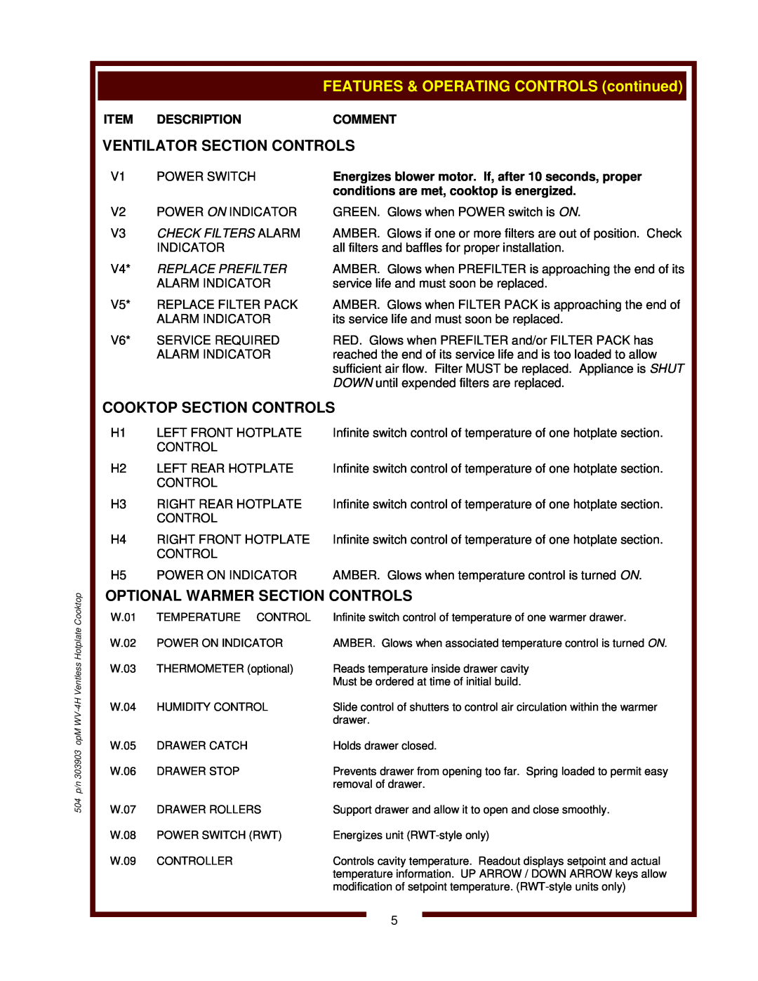
| VENTILATOR SECTION CONTROLS |
| ||
| V1 | POWER SWITCH | Energizes blower motor. If, after 10 seconds, proper |
|
|
|
| conditions are met, cooktop is energized. |
|
| V2 | POWER ON INDICATOR | GREEN. Glows when POWER switch is ON. |
|
| V3 | CHECK FILTERS ALARM | AMBER. Glows if one or more filters are out of position. Check |
|
|
| INDICATOR | all filters and baffles for proper installation. |
|
| V4* | REPLACE PREFILTER | AMBER. Glows when PREFILTER is approaching the end of its |
|
|
| ALARM INDICATOR | service life and must soon be replaced. |
|
| V5* | REPLACE FILTER PACK | AMBER. Glows when FILTER PACK is approaching the end of |
|
|
| ALARM INDICATOR | its service life and must soon be replaced. |
|
| V6* | SERVICE REQUIRED | RED. Glows when PREFILTER and/or FILTER PACK has |
|
|
| ALARM INDICATOR | reached the end of its service life and is too loaded to allow |
|
|
|
| sufficient air flow. Filter MUST be replaced. Appliance is SHUT |
|
|
|
| DOWN until expended filters are replaced. |
|
|
|
| ||
| COOKTOP SECTION CONTROLS |
| ||
| H1 | LEFT FRONT HOTPLATE | Infinite switch control of temperature of one hotplate section. |
|
|
| CONTROL |
|
|
| H2 | LEFT REAR HOTPLATE | Infinite switch control of temperature of one hotplate section. |
|
|
| CONTROL |
|
|
| H3 | RIGHT REAR HOTPLATE | Infinite switch control of temperature of one hotplate section. |
|
|
| CONTROL |
|
|
| H4 | RIGHT FRONT HOTPLATE | Infinite switch control of temperature of one hotplate section. |
|
|
| CONTROL |
|
|
| H5 | POWER ON INDICATOR | AMBER. Glows when temperature control is turned ON. |
|
| OPTIONAL WARMER SECTION CONTROLS |
| ||
| W.01 | TEMPERATURE CONTROL | Infinite switch control of temperature of one warmer drawer. |
|
| W.02 | POWER ON INDICATOR | AMBER. Glows when associated temperature control is turned ON. |
|
| W.03 | THERMOMETER (optional) | Reads temperature inside drawer cavity |
|
|
|
| Must be ordered at time of initial build. |
|
| W.04 | HUMIDITY CONTROL | Slide control of shutters to control air circulation within the warmer |
|
|
|
| drawer. |
|
| W.05 | DRAWER CATCH | Holds drawer closed. |
|
| W.06 | DRAWER STOP | Prevents drawer from opening too far. Spring loaded to permit easy |
|
|
|
| removal of drawer. |
|
| W.07 | DRAWER ROLLERS | Support drawer and allow it to open and close smoothly. |
|
| W.08 | POWER SWITCH (RWT) | Energizes unit |
|
| W.09 | CONTROLLER | Controls cavity temperature. Readout displays setpoint and actual |
|
|
|
| temperature information. UP ARROW / DOWN ARROW keys allow |
|
|
|
| modification of setpoint temperature. |
|
5