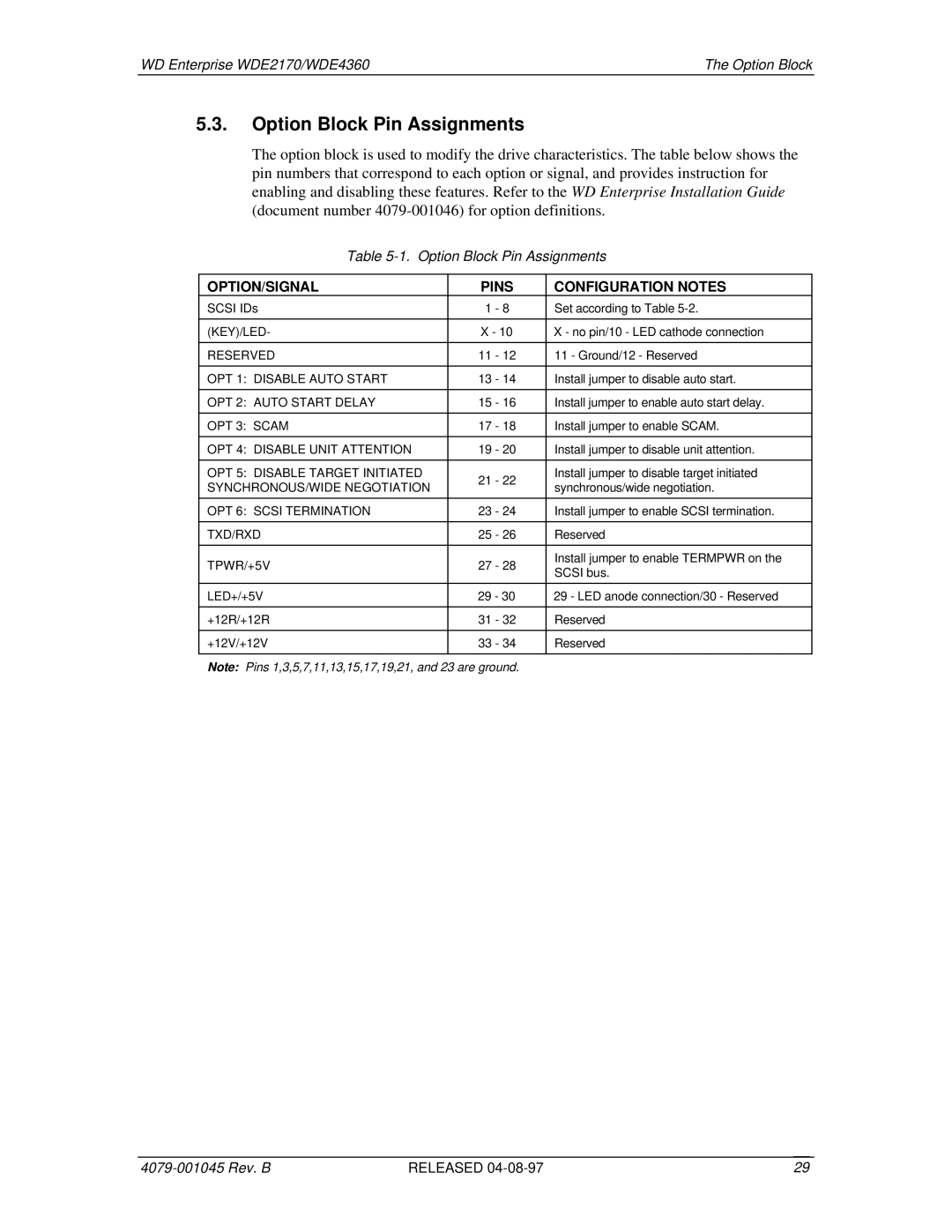
WDE4360, WDE2170 specifications
Western Digital, a leader in data storage, has introduced innovative products like the WDE2170 and WDE4360 drives, which showcase their commitment to cutting-edge technology and reliability. These models are designed for various applications, from personal computing to larger enterprise solutions.The WDE2170 is a 2TB hard drive positioned for consumers who require substantial storage for multimedia files, documents, and applications. Its interface features a SATA III connection, providing a robust data transfer rate that can reach up to 6Gbps. This speed ensures that users can access their files quickly and efficiently. Notably, the WDE2170 is equipped with a large cache size that enhances its performance during read and write operations. This makes it an excellent choice for gamers and content creators who need rapid access to their files.
On the other hand, the WDE4360 stands out as a 4TB offering, aimed at professionals and businesses requiring higher capacities. It utilizes advanced data management technologies to ensure data integrity and durability. With a focus on security features, the WDE4360 includes built-in encryption options to protect sensitive information. This model also utilizes advanced error recovery technology, which is vital for maintaining data integrity in RAID configurations or server setups.
Both models are built using Western Digital’s proprietary technologies that emphasize reliability and longevity. The drives are designed to withstand rigorous usage scenarios, making them perfect for environments where data access and protection are paramount. Additionally, these drives have low power consumption, which can help reduce operational costs, especially in larger installations.
The overall design of these drives is tailored for optimal performance and heat dissipation, ensuring that they can function effectively even under heavy loads. Western Digital's commitment to quality means that both the WDE2170 and WDE4360 undergo stringent testing processes to meet high standards of reliability before reaching the consumer market.
In conclusion, the Western Digital WDE2170 and WDE4360 are exceptional storage solutions, providing consumers and businesses with the speed, capacity, and reliability they need. These drives exemplify Western Digital's dedication to innovation and quality in the ever-evolving world of data storage. As data requirements continue to grow, these drives are sure to meet the demands of a diverse array of users.
