Special Applications

Combination Space Heating/Potable Water System

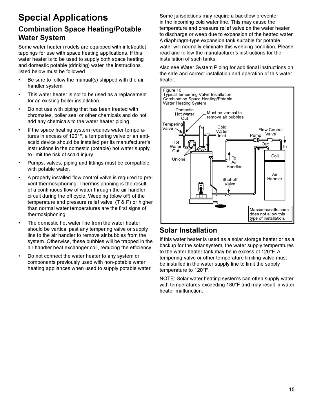
Some water heater models are equipped with inlet/outlet tappings for use with space heating applications. If this water heater is to be used to supply both space heating and domestic potable (drinking) water, the instructions listed below must be followed.

Be sure to follow the manual(s) shipped with the air handler system.

This water heater is not to be used as a replacement for an existing boiler installation.

Do not use with piping that has been treated with chromates, boiler seal or other chemicals and do not add any chemicals to the water heater piping.

If the space heating system requires water tempera- tures in excess of 120°F, a tempering valve or an anti- scald device should be installed per its manufacturer’s instructions in the domestic (potable) hot water supply to limit the risk of scald injury.

Pumps, valves, piping and fittings must be compatible with potable water.

A properly installed flow control valve is required to pre- vent thermosiphoning. Thermosiphoning is the result of a continuous flow of water through the air handler circuit during the off cycle. Weeping (blow off) of the temperature and pressure relief valve (T & P) or higher than normal water temperatures are the first signs of thermosiphoning.

The domestic hot water line from the water heater should be vertical past any tempering valve or supply line to the air handler to remove air bubbles from the system. Otherwise, these bubbles will be trapped in the air handler heat exchanger coil, reducing the efficiency.

Do not connect the water heater to any system or components previously used with non-potable water heating appliances when used to supply potable water.

Some jurisdictions may require a backflow preventer in the incoming cold water line. This may cause the temperature and pressure relief valve on the water heater to discharge or weep due to expansion of the heated water. A diaphragm-type expansion tank suitable for potable water will normally eliminate this weeping condition. Please read and follow the manufacturer’s instructions for the installation of such tanks.

Also see Water System Piping for additional instructions on the safe and correct installation and operation of this water heater.

Figure 16

Typical Tempering Valve Installation

Combination Space Heating/Potable

Water Heating System

Domestic


Must be vertical to


Hot Water


Out


remove air bubbles


Tempering


Cold


Valve


Flow Control


Water

Pump Valve


Inlet

Hot


Out


Water


In


Out


Coil


Unions

To


Air


Handler


Air


Shut-off

Handler


Valve


Massachusetts code does not allow this type of installation.

Solar Installation

If this water heater is used as a solar storage heater or as a backup for the solar system, the water supply temperatures to the water heater tank may be in excess of 120°F. A tempering valve or other temperature limiting valve must be installed in the water supply line to limit the supply temperature to 120°F.

NOTE: Solar water heating systems can often supply water with temperatures exceeding 180°F and may result in water heater malfunction.

15

Page 15
Image 15
Whirlpool W10100910, 315420-000 Special Applications, Combination Space Heating/Potable Water System, Solar Installation

W10100910, 315420-000 specifications

Whirlpool 315420-000 and W10100910 are parts designed to enhance the efficiency and performance of various Whirlpool appliances, particularly in the realm of washing machines and dryers. These components have gained attention for their durability, reliability, and ability to improve the overall user experience.

One of the main features of the Whirlpool 315420-000 is its role as a water inlet valve. This essential component regulates water entry into the washing machine, ensuring that the right amount of water is available for each cycle. The valve is designed to replace old or malfunctioning units, restoring the washing machine’s functionality. Its construction typically includes high-quality materials that resist wear and corrosion, contributing to a longer lifespan and dependable operation.

The W10100910 part often refers to the dryer thermal fuse, a critical safety component that prevents overheating. When the dryer temperature exceeds safe levels, this fuse blows to cut off power, protecting the appliance and the surrounding area from potential fires. The reliable operation of this fuse is essential for maintaining safety standards in the home and extending the life of the dryer.

Both parts feature user-friendly designs, allowing for straightforward installation. Usually, homeowners or technicians can easily replace them without needing extensive tools or specialized training. This accessibility makes it convenient for individuals looking to perform DIY repairs, ultimately saving time and money on professional service.

In terms of technology, these components highlight Whirlpool's commitment to innovation and quality. For instance, the water inlet valve is engineered to accommodate variable water pressures, ensuring consistent performance even in different home plumbing situations. The thermal fuse utilizes advanced material engineering to ensure rapid response to temperature increases, enhancing the safety protocols of modern dryers.

Overall, the Whirlpool 315420-000 and W10100910 are excellent representations of the brand’s dedication to customer satisfaction and appliance longevity. Their main features focus on reliability, ease of installation, and safety, making them essential components for maintaining optimal performance in Whirlpool washing machines and dryers. Whether you're a homeowner looking to perform maintenance or a service technician tasked with repairs, these parts play a crucial role in ensuring that appliances run smoothly and efficiently.