Replacement Parts

IMPORTANT: The following maintenance procedures are for the Flame LockSafety System components and should be performed by a qualified person.

Replacement parts may be ordered through your plumber or the local distributor. Parts will be shipped at prevailing prices and billed accordingly. When ordering replacement parts, always have the following information ready:

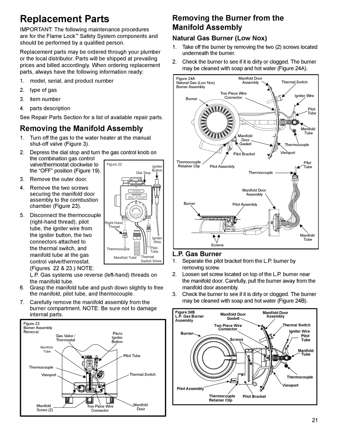
Removing the Burner from the Manifold Assembly

Natural Gas Burner (Low Nox)

1.Take off the burner by removing the two (2) screws located underneath the burner.

2.Check the burner to see if it is dirty or clogged. The burner may be cleaned with soap and hot water (Figure 24A).

1.model, serial, and product number

2.type of gas

3.item number

Figure 24A

Manifold Door

Thermal Switch

Natural Gas (Low Nox)

Assembly

Burner Assembly


Two Piece Wire

Igniter Wire

Burner

Connector


4.

parts description


Pilot

See Repair Parts Section for a list of available repair parts.


Tube


Removing the Manifold Assembly


Manifold


Manifold

Tube

1. Turn off the gas to the water heater at the manual


Door


shut-off valve (Figure 3).


Gasket

Thermocouple

2. Depress the dial stop and turn the gas control knob on


Pilot Bracket

Viewport


the combination gas control


Thermocouple


Pilot


valve/thermostat clockwise to

Figure 22


Igniter

Retainer Clip

Pilot Assembly

Tube


the “OFF” position (Figure 19).


Button


Thermocouple


Dial Stop


3. Remove the outer door.


4.

Remove the two screws


U N I T R O L


Manifold Door


securing the manifold door


WARNING


Assembly


READ ALL INSTRUCTIONS


assembly to the combustion


BEFORE


LIGHTING


WAR


Burner

Pilot Assembly


chamber (Figure 23).


T I


T


U


M


HO


A

O


5.

Disconnect the thermocouple

R


C


N


O

T

W

H


S


Y


B


H

A

R

S


R


E


E

T


OT TE

E


U


V


R

R E

R

EA


J


A


T

I

I NCR

IN


S


SK

O


C


H


LD


OITA


AW


F SCA


(right-hand thread), pilot


N


Right-Hand


tube, the igniter wire from

Thread


the igniter button, the two


Igniter


Manifold

connectors attached to


Tube


Wire


Screws


the thermal switch, and


Thermocouple

Pilot


manifold tube at the gas


Tube

L.P. Gas Burner


Manifold Tube

Thermal


control valve/thermostat.


Switch Wires

1. Separate the pilot bracket from the L.P. burner by

(Figures

22 & 23.) NOTE:


removing screw.


L.P. Gas systems use reverse (left-hand) threads on

2. Loosen set screw located on top of the L.P. burner near

the manifold tube.


the manifold door. Carefully, pull the burner away from the

6. Grasp the manifold tube and push down slightly to free

manifold door assembly.


the manifold, pilot tube, and thermocouple.


3. Check the burner to see if it is dirty or clogged. The burner

7. Carefully remove the manifold assembly from the

may be cleaned with soap and hot water (Figure 24B).

burner compartment. NOTE: Be sure not to damage

Figure 24B


Manifold Door

internal parts.


Manifold Door


L.P. Gas Burner

Assembly


Assembly

Gasket


Figure 23


Thermal Switch


Two Piece Wire


Burner Assembly


Connector


Igniter Wire

Removal


Piezo


Burner


Gas Valve /


Pilot


Igniter


Screws


Thermostat


Tube


Button


Manifold


Manifold

Tube


Pilot Tube


Tube


WARNING


Thermocouple

I

O


Viewport


Thermal Switch


Thermocouple


Pilot Assembly


Viewport


Thermocouple

Pilot Bracket


Manifold


Retainer Clip


Manifold


Two Piece Wire


Screw (2)


Connector


Door


21

Page 21
Image 21
Whirlpool W10100910 warranty Replacement Parts, Removing the Burner from the Manifold Assembly, Natural Gas Burner Low Nox

W10100910, 315420-000 specifications

Whirlpool 315420-000 and W10100910 are parts designed to enhance the efficiency and performance of various Whirlpool appliances, particularly in the realm of washing machines and dryers. These components have gained attention for their durability, reliability, and ability to improve the overall user experience.

One of the main features of the Whirlpool 315420-000 is its role as a water inlet valve. This essential component regulates water entry into the washing machine, ensuring that the right amount of water is available for each cycle. The valve is designed to replace old or malfunctioning units, restoring the washing machine’s functionality. Its construction typically includes high-quality materials that resist wear and corrosion, contributing to a longer lifespan and dependable operation.

The W10100910 part often refers to the dryer thermal fuse, a critical safety component that prevents overheating. When the dryer temperature exceeds safe levels, this fuse blows to cut off power, protecting the appliance and the surrounding area from potential fires. The reliable operation of this fuse is essential for maintaining safety standards in the home and extending the life of the dryer.

Both parts feature user-friendly designs, allowing for straightforward installation. Usually, homeowners or technicians can easily replace them without needing extensive tools or specialized training. This accessibility makes it convenient for individuals looking to perform DIY repairs, ultimately saving time and money on professional service.

In terms of technology, these components highlight Whirlpool's commitment to innovation and quality. For instance, the water inlet valve is engineered to accommodate variable water pressures, ensuring consistent performance even in different home plumbing situations. The thermal fuse utilizes advanced material engineering to ensure rapid response to temperature increases, enhancing the safety protocols of modern dryers.

Overall, the Whirlpool 315420-000 and W10100910 are excellent representations of the brand’s dedication to customer satisfaction and appliance longevity. Their main features focus on reliability, ease of installation, and safety, making them essential components for maintaining optimal performance in Whirlpool washing machines and dryers. Whether you're a homeowner looking to perform maintenance or a service technician tasked with repairs, these parts play a crucial role in ensuring that appliances run smoothly and efficiently.