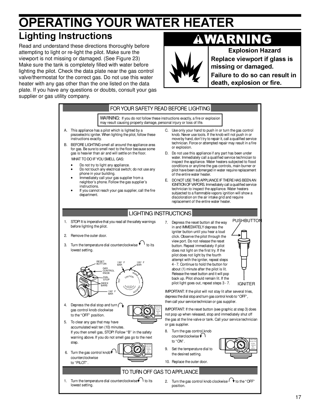
OPERATING YOUR WATER HEATER

Lighting Instructions

Read and understand these directions thoroughly before attempting to light or re-light the pilot. Make sure the viewport is not missing or damaged. (See Figure 23) Make sure the tank is completely filled with water before lighting the pilot. Check the data plate near the gas control valve/thermostat for the correct gas. Do not use this water heater with any gas other than the one listed on the data plate. If you have any questions or doubts, consult your gas supplier or gas utility company.

WARNING

Explosion Hazard

Replace viewport if glass is missing or damaged.

Failure to do so can result in death, explosion or fire.

FOR YOUR SAFETY READ BEFORE LIGHTING

WARNING: If you do not follow these instructions exactly, a fire or explosion may result causing property damage, personal injury or loss of life.

A.This appliance has a pilot which is lighted by a piezoelectric igniter. When lighting the pilot, follow these instructions exactly.

B.BEFORE LIGHTING smell all around the appliance area for gas. Be sure to smell next to the floor because some gas is heavier than air and will settle on the floor.

WHAT TO DO IF YOU SMELL GAS:

ϖDo not try to light any appliance.

ϖDo not touch any electrical switch; do not use any phone in your building.

ϖImmediately call your gas supplier from a neighbor’s phone. Follow the gas supplier’s instructions.

ϖIf you cannot reach your gas supplier, call the fire department.

C.Use only your hand to push in or turn the gas control knob. Never use tools. If the knob will not push in or move by hand, don’t try to repair it, call a qualified service technician. Force or attempted repair may result in a fire or explosion.

D.Do not use this appliance if any part has been under water. Immediately call a qualified service technician to inspect the appliance. Water heaters subjected to flood conditions or anytime the gas controls, main burner or pilot have been submerged in water require replacement of the entire water heater.

E.DO NOT USE THIS APPLIANCE IF THERE HAS BEEN AN IGNITION OF VAPORS. Immediately call a qualified service technician to inspect the appliance. Water heaters subjected to a flammable vapors ignition will show a discoloration on the air intake grid and require replacement of the entire water heater.

LIGHTING INSTRUCTIONS

1.STOP! It is imperative that you read all the safety warnings before lighting the pilot.

2.Remove the outer door.

3.Turn the temperature dial counterclockwise to its lowest setting.


RESET

130° F


120° F


BUTTON

BAR


BAR


GAS


CONTROL


WA


KNOB


R


DIAL


AUTIO


M


READUNITROL

C


N


STOP

T


O


H


ALL


BEFOREWARNING

INDEX


INSTRUCTIONS

W

H

R


T


LIGHTING

BARS

T

A

SES


Y


V

H


H


T


O TTE

R


WA


E


E


A

JU


A


R


R INCRE


C


R


IS


IN


7.Depress the reset button all the way in and IMMEDIATELY depress the igniter button until you hear a loud click. Observe the pilot through the view port. Do not release the reset button. Repeat immediately if pilot does not light on the first try. If the pilot does not light by the fourth attempt with the igniter, repeat steps 4 - 7. Continue to hold the button for about (1) minute after the pilot is lit. Release the reset button and it will pop back up. Pilot should remain lit. If the pilot light goes out, repeat steps 3 - 7.

PUSHBUTTON

IGNITER

C

M


K OF SCALD


A

AUTIO


N


130° F

T


OI


N


V

BAR


CA


O I

TA


4. Depress the dial stop and turn


N O

CAUTION

gas control knob clockwise

O

DAMAGE


P


DO NOT PRY


ON DIAL


I


L


to the “OFF” position.

T

OFF

WILL


RESULT

5.To clear any gas that may have accumulated wait ten (10) minutes.

If you then smell gas, STOP! Follow “B” in the safety warning above. If you do not smell gas go to the next step.


CAUTION


DO NOT PRY


O

F

ON DIAL

6. Turn the gas control knob

F

DAMAGE

N

PILOT


O

WILL


RESULT

counterclockwise


to “PILOT”.


IMPORTANT: If the pilot will not stay lit after several tries, depress the dial stop and turn gas control knob to “OFF”, then call your service technician or gas supplier.

IMPORTANT: If the reset button (see graphic at step 3) does not pop up when released, stop and immediately shut off the gas at the line valve or tank. Call your service technician or gas supplier.

8.Turn the gas control knob counterclockwise

to “ON”.

T

ON DIAL


FFO

CAUTION


DO NOT PRY


O

DAMAGE


L

9. Set the temperature dial to

I

WILL

O N


P

RESULT

the desired setting.


10. Replace the outer door.

TO TURN OFF GAS TO APPLIANCE

1. Turn the temperature dial counterclockwise

to its

2. Turn the gas control knob clockwise

to the “OFF”

lowest setting.


position.


17

Page 17
Image 17
Whirlpool W10100910, 315420-000 warranty Operating Your Water Heater, Lighting Instructions

W10100910, 315420-000 specifications

Whirlpool 315420-000 and W10100910 are parts designed to enhance the efficiency and performance of various Whirlpool appliances, particularly in the realm of washing machines and dryers. These components have gained attention for their durability, reliability, and ability to improve the overall user experience.

One of the main features of the Whirlpool 315420-000 is its role as a water inlet valve. This essential component regulates water entry into the washing machine, ensuring that the right amount of water is available for each cycle. The valve is designed to replace old or malfunctioning units, restoring the washing machine’s functionality. Its construction typically includes high-quality materials that resist wear and corrosion, contributing to a longer lifespan and dependable operation.

The W10100910 part often refers to the dryer thermal fuse, a critical safety component that prevents overheating. When the dryer temperature exceeds safe levels, this fuse blows to cut off power, protecting the appliance and the surrounding area from potential fires. The reliable operation of this fuse is essential for maintaining safety standards in the home and extending the life of the dryer.

Both parts feature user-friendly designs, allowing for straightforward installation. Usually, homeowners or technicians can easily replace them without needing extensive tools or specialized training. This accessibility makes it convenient for individuals looking to perform DIY repairs, ultimately saving time and money on professional service.

In terms of technology, these components highlight Whirlpool's commitment to innovation and quality. For instance, the water inlet valve is engineered to accommodate variable water pressures, ensuring consistent performance even in different home plumbing situations. The thermal fuse utilizes advanced material engineering to ensure rapid response to temperature increases, enhancing the safety protocols of modern dryers.

Overall, the Whirlpool 315420-000 and W10100910 are excellent representations of the brand’s dedication to customer satisfaction and appliance longevity. Their main features focus on reliability, ease of installation, and safety, making them essential components for maintaining optimal performance in Whirlpool washing machines and dryers. Whether you're a homeowner looking to perform maintenance or a service technician tasked with repairs, these parts play a crucial role in ensuring that appliances run smoothly and efficiently.