All Air from Outdoors

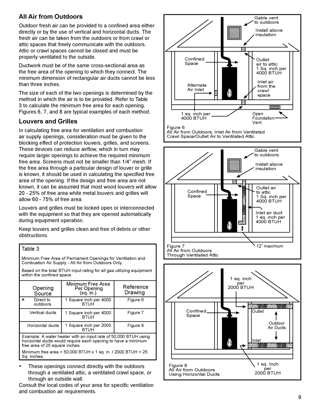
Outdoor fresh air can be provided to a confined area either directly or by the use of vertical and horizontal ducts. The fresh air can be taken from the outdoors or from crawl or attic spaces that freely communicate with the outdoors. Attic or crawl spaces cannot be closed and must be properly ventilated to the outside.

Ductwork must be of the same cross-sectional area as the free area of the opening to which they connect. The minimum dimension of rectangular air ducts cannot be less than three inches.

The size of each of the two openings is determined by the method in which the air is to be provided. Refer to Table 3 to calculate the minimum free area for each opening. Figures 6, 7, and 8 are typical examples of each method.

Louvers and Grilles

In calculating free area for ventilation and combustion air supply openings, consideration must be given to the blocking effect of protection louvers, grilles, and screens. These devices can reduce airflow, which in turn may require larger openings to achieve the required minimum free area. Screens must not be smaller than 1/4” mesh. If the free area through a particular design of louver or grille is known, it should be used in calculating the specified free area of the opening. If the design and free area are not known, it can be assumed that most wood louvers will allow 20 - 25% of free area while metal louvers and grilles will allow 60 - 75% of free area.

Louvers and grilles must be locked open or interconnected with the equipment so that they are opened automatically during equipment operation.

Keep louvers and grilles clean and free of debris or other obstructions.

Table 3

Minimum Free Area of Permanent Openings for Ventilation and Combustion Air Supply - All Air from Outdoors Only.

Based on the total BTUH input rating for all gas utilizing equipment within the confined space.

Opening

Minimum Free Area

Reference

Per Opening

Source

(sq. in.)

Drawing

Direct to

1 Square inch per 4000

Figure 6

outdoors

BTUH


Vertical ducts

1 Square inch per 4000

Figure 7


BTUH


Horizontal ducts

1 Square inch per 2000

Figure 8


BTUH


Example: A water heater with an input rate of 50,000 BTUH using horizontal ducts would require each opening to have a minimum free area of 25 square inches.

Minimum free area = 50,000 BTUH x 1 sq. in. / 2000 BTUH = 25 Sq. Inches.

*These openings connect directly with the outdoors through a ventilated attic, a ventilated crawl space, or through an outside wall.

Consult the local codes of your area for specific ventilation and combustion air requirements.


Gable vent


to outdoors


Install above


insulation

Confined

Outlet

Space

air to attic


1 Sq. inch per


4000 BTUH

Alternate

Inlet air

from the

Air Inlet

crawl


space

1 sq. inch per

Open

4000 BTUH

Foundation


Vent

Figure 6

All Air from Outdoors; Inlet Air from Ventilated

Crawl Space/Outlet Air to Ventilated Attic


Gable vent


to outdoors


Install above


insulation

Confined

Outlet air

to attic

Space

1 Sq. inch per


4000 BTUH


Inlet air duct


1 sq. inch per


4000 BTUH

Figure 7

12” maximum

All Air from Outdoors


Through Ventilated Attic


1 sq. inch


per


2000 BTUH

Confined

Outlet

Space


Outdoor


Air Ducts


Inlet

Figure 8

1 sq. Inch

All Air from Outdoors

per

Using Horizontal Ducts

2000 BTUH

9

Page 9
Image 9
Whirlpool W10100910, 315420-000 warranty All Air from Outdoors, Louvers and Grilles

W10100910, 315420-000 specifications

Whirlpool 315420-000 and W10100910 are parts designed to enhance the efficiency and performance of various Whirlpool appliances, particularly in the realm of washing machines and dryers. These components have gained attention for their durability, reliability, and ability to improve the overall user experience.

One of the main features of the Whirlpool 315420-000 is its role as a water inlet valve. This essential component regulates water entry into the washing machine, ensuring that the right amount of water is available for each cycle. The valve is designed to replace old or malfunctioning units, restoring the washing machine’s functionality. Its construction typically includes high-quality materials that resist wear and corrosion, contributing to a longer lifespan and dependable operation.

The W10100910 part often refers to the dryer thermal fuse, a critical safety component that prevents overheating. When the dryer temperature exceeds safe levels, this fuse blows to cut off power, protecting the appliance and the surrounding area from potential fires. The reliable operation of this fuse is essential for maintaining safety standards in the home and extending the life of the dryer.

Both parts feature user-friendly designs, allowing for straightforward installation. Usually, homeowners or technicians can easily replace them without needing extensive tools or specialized training. This accessibility makes it convenient for individuals looking to perform DIY repairs, ultimately saving time and money on professional service.

In terms of technology, these components highlight Whirlpool's commitment to innovation and quality. For instance, the water inlet valve is engineered to accommodate variable water pressures, ensuring consistent performance even in different home plumbing situations. The thermal fuse utilizes advanced material engineering to ensure rapid response to temperature increases, enhancing the safety protocols of modern dryers.

Overall, the Whirlpool 315420-000 and W10100910 are excellent representations of the brand’s dedication to customer satisfaction and appliance longevity. Their main features focus on reliability, ease of installation, and safety, making them essential components for maintaining optimal performance in Whirlpool washing machines and dryers. Whether you're a homeowner looking to perform maintenance or a service technician tasked with repairs, these parts play a crucial role in ensuring that appliances run smoothly and efficiently.