Manuals
/
Whirlpool
/
Kitchen Appliance
/
Ventilation Hood
Whirlpool
36 Make Electrical Connections for In-Line, Blower Motor System, Complete Preparation
Models:
36
48
1
11
36
36
Download
36 pages
39.23 Kb
8
9
10
11
12
13
14
15
Page 11
Image 11
Page 10
Page 12
Page 11
Image 11
Page 10
Page 12
Contents
POUR UTILISATION RÉSIDENTIELLE UNIQUEMENT
IMPORTANT READ AND SAVE THESE INSTRUCTIONS
FOR RESIDENTIAL USE ONLY
IMPORTANT LIRE ET CONSERVER CES INSTRUCTIONS
TABLE OF CONTENTS
RANGE HOOD SAFETY
TABLE DES MATIÈRES
DANGER
READ AND SAVE THESE INSTRUCTIONS
IMPORTANT SAFETY INSTRUCTIONS
Tools and Parts
INSTALLATION REQUIREMENTS
For Mobile Home Installations
Cabinet Dimensions
Makeup air
Product Dimensions
Cold weather installations
Venting Requirements
C D B A
Electrical Requirements
Calculating Vent System Length
Example vent system
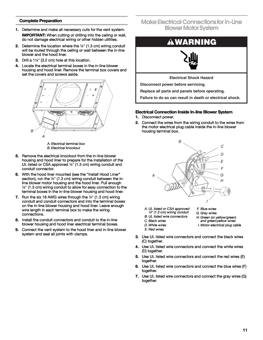
Complete Preparation
INSTALLATION INSTRUCTIONS
Prepare Location
Hood Liner Support Preparation
B A D E C
Install Hood Liner Internal Blower Motor
Install Range Hood Liner
Prepare the Internal Blower System
C B A
Install Hood Liner Internal Blower Motor
Single Blower Motor Assembly
Dual Blower Motor Assembly
Prepare for Mounting the In-LineBlower System
Install Hood Liner In-LineExternal Type
Install In-lineBlower System
Blower Motor
Complete Preparation
Make Electrical Connections for In-Line
Blower Motor System
Electrical Connection Inside In-lineBlower System
Electrical Shock Hazard
Make Electrical Power Supply Connection
to Hood Liner
Disconnect power before servicing
A E D A
Complete Installation and Check
Operation
A B CA
Operating the fan
Adjusting the fan
RANGE HOOD USE
Range Hood Controls
Metal Grease Filter
Cleaning
RANGE HOOD CARE
Exterior Surfaces
Motor Resistance Ohms
WIRING DIAGRAM
Motor Characteristics
SE112A
In the U.S.A
ASSISTANCE OR SERVICE
Accessories
If you need replacement parts
This limited warranty does not cover
WHIRLPOOL CORPORATION MAJOR APPLIANCE WARRANTY
LIMITED WARRANTY
ITEMS EXCLUDED FROM WARRANTY
DANGER AVERTISSEMENT
SÉCURITÉ DE LA HOTTE DE CUISINIÈRE
LIRE ET CONSERVER CES INSTRUCTIONS
IMPORTANTES INSTRUCTIONS DE SÉCURITÉ
Dimensions du placard
EXIGENCES DINSTALLATION
Exigences demplacement
Installation dans une résidence mobile
Air d’appoint
Dimensions du produit
Installations pour régions à climat froid
Exigences concernant l’évacuation
Décharge à travers le toit
Spécifications électriques
Exemple de circuit d’évacuation
Calcul de la longueur du circuit d’évacuation
Préparation du support de la caisse de la hotte
INSTRUCTIONS D’INSTALLATION
Préparation de lemplacement
AVERTISSEMENT
Préparation du système de ventilation interne
Installation dumoteurdu ventilateur interne
Installation de la caisse de la hotte
de la caisse de la hotte
C B A
Ensemble à un seul moteur-ventilateur
Ensemble à deux moteurs-ventilateurs
A B C D
Installation du système de ventilation en ligne
Préparation du système de ventilation en ligne
AVERTISSEMENT
C D E F G H
AVERTISSEMENT
Achever la préparation
C D E F G H
AVERTISSEMENT
Risque de choc électrique
Relier le ventilateur à la terre
fonctionnement
Achever linstallation et vérifier le
Réalisation des connexions de
l’alimentation électrique à la caisse de la hotte
Fonctionnement du ventilateur
Commandes de la hotte de cuisinière
Commande de la lampe
UTILISATION DE LA HOTTE
Surfaces externes
Remplacement d’une lampe à halogène
ENTRETIEN DE LA HOTTE
Nettoyage
SE112A
SCHÉMA DE CÂBLAGE
Résistance du moteur ohms
Caractéristiques du moteur
Si vous avez besoin de pièces de rechange
ASSISTANCE OU SERVICE
Accessoires
Au Canada
ARTICLES EXCLUS DE LA GARANTIE
GARANTIE DES GROS APPAREILS MÉNAGERS
WHIRLPOOL CORPORATION
GARANTIE LIMITÉE
All rights reserved
W10331011B
2011 Whirlpool Corporation
2/11
Top
Page
Image
Contents