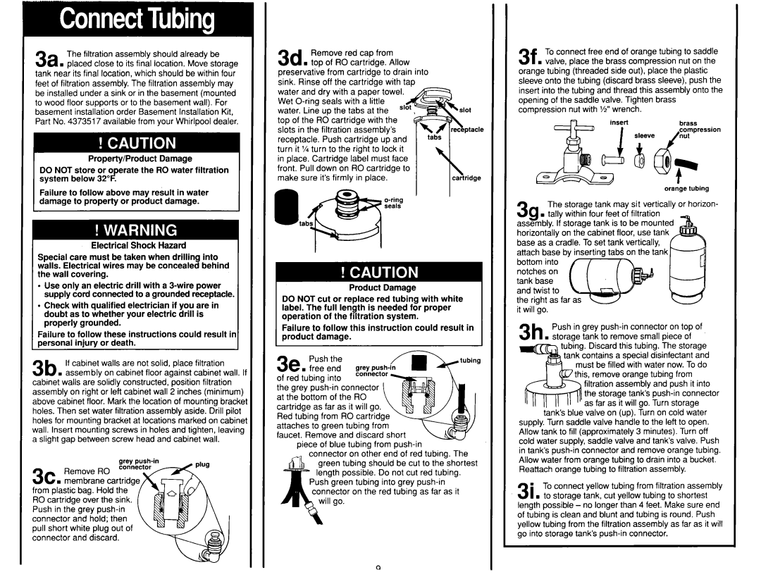
The filtration assembly should already be
. placed close to its final location. Move storage tank near its final location, which should be within four feet of filtration assembly. The filtration assembly may be installed under a sink or in the basement (mounted to wood floor supports or to the basement wall). For basement installation order Basement Installation Kit, Part No. 4373517 available from your Whirlpool dealer.
Property/Product Damage
DO NOT store or o erate the RO water filtration system below 32 2 .
Failure to follow above may result in water damage to property or product damage.
Electrical Shock Hazard
Special care must be taken when drilling into walls. Electrical wires may be concealed behind the wall covering.
l Use only an electric drill with a
l Check with qualified electrician if you are in doubt as to whether your electric drill is properly grounded.
Failure to follow these instructions could result ir oersonal iniurv or death.
3b If cabinet walls are not solid, place filtration
. assembly on cabinet floor against cabinet wall. If cabinet walls are solidly constructed, position filtration assembly on right or left cabinet wall 2 inches (minimum) above cabinet floor. Mark the location of mounting brackei holes. Then set water filtration assembly aside. Drill pilot holes for mounting bracket at locations marked on cabinet wall. Insert mounting screws in holes and tighten, leaving a slight gap between screw head and cabinet wall.
grey
3c Remove RO connector
. membrane cartridg from plastic bag. Hold the RO cartridge over the sink. Push in the grey
Remove | red cap | from |
| |
3d . top of RO cartridge. Allow |
| |||
preservative from cartridge to drain into |
| |||
sink. Rinse off the cartridge with tap |
| |||
water and dry with a paper towel. |
| |||
Wet |
| |||
water. Line up the tabs at the |
| |||
top of the Rd cartridge with the |
| |||
slots in the filtration assembly’s | t&is | |||
receptacle. | Push | cartridge | up and | |
turn it % turn to the right to lock it |
| |||
in place. Cartridge label must face |
| |||
front. Pull down on RO cartridge to |
| |||
make sure | it’s firmly in place. | cartridge | ||
\
Product Damage
DO NOT cut or replace red tubing with white label. The full length is needed for proper operation of the filtration system.
Failure to follow this instruction could result in product damage.
eq | Push the |
| |
v s free | end | grey | |
of red | tubing | into |
|
the grey
piece of blue tubing from
ther end of red tubing. The should be cut to the shortest le. Do not cut red tubing. ing into grey
he red tubing as far as it
3f To connect free end of orange tubing to saddle
. valve, place the brass compression nut on the orange tubing (threaded side out), place the plastic sleeve onto the tubing (discard brass sleeve), push the insert into the tubing and thread this assembly onto the opening of the saddle valve. Tighten brass compression nut with Yz” wrench.
brass
orange tubing
3sThe storage tank may sit vertically or horizon-
. tally within four feet of filtration assembly. If storage tank is to be mounted horizontally on the cabinet floor, use tank base as a cradle. To set tank vertically,
Push in grey
tubing. Discard this tubing. The storage tank contains a special disinfectant and
ust be filled with water now. To do is, remove orange tubing from filtration assembly and push it into the storage tanks
tank’s blue valve on (up). Turn on cold water supply. Turn saddle valve handle to the left to open. Allow tank to fill (approximately 3 minutes). Turn off cold water supply, saddle valve and tanks valve. Push in tank’s
31n To connect yellow tubing from filtration assembly
. to storage tank, cut yellow tubing to shortest length possible - no longer than 4 feet. Make sure end of tubing is clean and blunt and tubing is round. Push yellow tubing from the filtration assembly as far as it will go into storage tank’s
