Remove Jumper Wire between RH & RC

WIRING DIAGRAMS

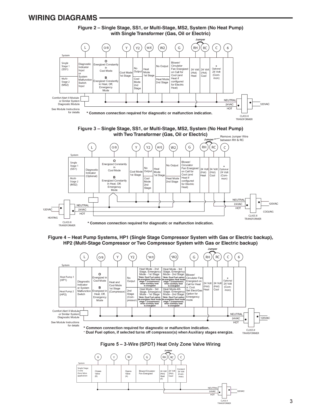
Figure 2 – Single Stage, SS1, or Multi-Stage, MS2, System (No Heat Pump)

with Single Transformer (Gas, Oil or Electric)

Jumper


L

O/B

Y

Y2

W/E

W2

G

RH

RC

C

6

System


Single

Diagnostic

O


Blower/


Energized Constantly


Stage 1


No Output

Circulator


*


Indicator

in


No

Heat

24 Volt

24 Volt


(SS1)

Input

Cool Mode


Fan Energized

Optional


Cool Mode

Output

Mode


on Call for

(Hot)

(Hot)

24 Volt


or


System

B

1st Stage


1st Stage


Cool (and

Heat

Cool

(Com-


Multi-


Malfunction


Cool


Heat Mode

Heat if


mon)


Stage 2

Energized Constantly


configured


Switch

in Heat, Off,


Mode


2nd Stage


(MS2)

Input


2nd


for Electric


Emergency


Stage


Heat)


Mode


Comfort Alert II Module

or Similar System

Diagnostic Module

See Module Instructions

for details

NEUTRAL


24VAC

120VAC

HOT


* Common connection required for diagnostic or malfunction indication.


CLASS II


TRANSFORMER


Figure 3 – Single Stage, SS1, or Multi-Stage, MS2, System (No Heat Pump)

with Two Transformer (Gas, Oil or Electric)

Jumper


L


O/B

Y

Y2

W/E

W2

G

RH

RC

C


System


Single


O


Blower/


Energized Constantly


Stage 1


No Output

Circulator


*


in


No


(SS1)


Diagnostic


Heat


Fan Energized

24 Volt

24 Volt


Cool Mode

Cool Mode

Output


on Call for

Optional


Indicator


Mode


(Hot)

(Hot)

24 Volt


(Optional)


B

1st Stage


1st Stage


Cool (and

Heat

Cool

(Com-


Multi-


Cool


Heat Mode

Heat if


mon)


Stage 2


Energized Constantly


Mode


2nd Stage

configured


(MS2)


in Heat, Off,


2nd


for Electric


Emergency


Stage


Heat)


Mode


NEUTRAL


24VAC


120VAC


NEUTRAL


HOT


120VAC


24VAC


COOLING


HOT


CLASS II


HEATING


TRANSFORMER


CLASS II


* Common connection required for diagnostic or malfunction indication.


TRANSFORMER


Figure 4 – Heat Pump Systems, HP1 (Single Stage Compressor System with Gas or Electric backup),

HP2 (Multi-Stage Compressor or Two Compressor System with Gas or Electric backup)


Jumper


L

O/B

Y

Y2

+W/E

+W2

G

RH RC

C

6

System


Heat Mode - 2nd

Heat Mode - 3rd


O


Stage, Emergency

Stage, Emergency


Heat Pump 1


Mode - 1st Stage

Mode - 2nd Stage

Blower/


Energized in


No

+Note: Dual Fuel option

+Note: Dual Fuel option

Circulator Fan


*


(HP1)

Diagnostic

Heat and

de-energizes Heat mode

de-energizes Heat mode


Cool Mode

Output

stage 1 (compressor)

stage 1 (compressor)

Energized on

24 Volt

24 Volt

Optional


Indicator


Cool Mode


when auxiliary heat

when auxiliary heat

Call for Heat

24 Volt


B


is energized

is energized

or Cool.

(Hot)

(Hot)

(Com-


or System

1st Stage


Heat Mode - 3rd

Heat Mode-4th

Heat

Cool


Heat Pump 2

Malfunction

Energized in

(Compressor)

2nd

Set Elect/Gas

mon)


Stage, Emergency

Stage. Emergency


(HP2)

Switch

Heat, Off,


Stage

Mode - 1st Stage

Mode - 2nd Stage

Option for


Emergency


(Com-

+Note: Dual Fuel option

+Note: Dual Fuel option

Emergency


Mode


pressor)

de-energizes Heat mode

de-energizes Heat mode

mode


stage 1 (compressor)

stage 1 (compressor)


when auxiliary heat

when auxiliary heat


is energized

is energized


Comfort Alert II Module


or Similar System


NEUTRAL


Diagnostic Module


24VAC


See Module Instructions


HOT


for details

* Common connection required for diagnostic or malfunction indication.


CLASS II


+ Dual Fuel option, if selected turns off compressor(s) when Auxiliary stages energize.


TRANSFORMER

120VAC

Figure 5 – 3-Wire (SPDT) Heat Only Zone Valve Wiring

Jumper


6

Y

W

G

RH

RC

C

System


Single Stage


Constant

3-wire

Closes


Opens

Blower/Circulator

24 Volt

24 Volt


24 Volt

Zone Valve

Valve


Valve

Fan Energized

(Hot)

(Hot)

(Com-

application

(6)


(4)


Heat

Cool

mon)


(5)


NEUTRAL


24VAC


120VAC


HOT


3


CLASS II


TRANSFORMER

Page 3
Image 3
White Rodgers 1F95EZ-0671 specifications Wiring Diagrams, Wire Spdt Heat Only Zone Valve Wiring

1F95EZ-0671 specifications

The White Rodgers 1F95EZ-0671 is an advanced programmable thermostat designed to offer convenience and control over home heating and cooling systems. It is an ideal choice for homeowners looking to optimize their energy usage while maintaining comfortable living conditions.

One of the standout features of the 1F95EZ-0671 is its user-friendly interface, which includes a large, easy-to-read touchscreen display. The intuitive design allows users to navigate through settings effortlessly, making it accessible for individuals of all ages. The display is backlit, ensuring visibility even in low light conditions, which adds to its ease of use.

This thermostat supports both heating and cooling systems, including conventional systems as well as heat pumps, making it versatile for various home setups. Its compatibility with 24V systems further enhances its appeal for homeowners looking to upgrade their existing thermostats without extensive modifications.

Another significant technological advancement in the 1F95EZ-0671 is its Wi-Fi connectivity. This feature allows users to control their home climate remotely via a smartphone app, providing unparalleled convenience. Whether at work or on vacation, users can adjust their home temperature settings, ensuring optimal comfort upon their return. The app also enables users to monitor energy usage, helping them make informed decisions about their heating and cooling practices.

Energy efficiency is a key focus of the 1F95EZ-0671. It features a 7-day programmable schedule, allowing users to set heating and cooling times based on their specific routines. By programming temperature changes for different times of the day, users can significantly reduce energy consumption and lower utility bills. The thermostat also includes a vacation mode, which temporarily overrides the regular schedule, further optimizing energy savings when the home is unoccupied.

Additionally, the 1F95EZ-0671 is equipped with Smart Alerts that notify users of extreme temperatures, helping to prevent potential problems and ensure a safe home environment. With its combination of advanced features and user-centric design, the White Rodgers 1F95EZ-0671 provides an effective solution for modern temperature control, making it a valuable addition to any home.