CONFIGURATION
CONFIGURATION
CONFIGURACIÓN
JUMPERS/FILS DE CONNEXION/CABLES DE PUENTE
Before turning power on to the system, the jumpers on the back of the thermostat must be configured to operate correctly with the system equipment.
This thermostat is configured from the factory to operate a standard fossil fuel (gas, oil, etc.), forced hot air system with a single stage air conditioning compressor and fan. This is the correct configuration for any system that DOES NOT require the thermostat to energize the fan on a call for heat.
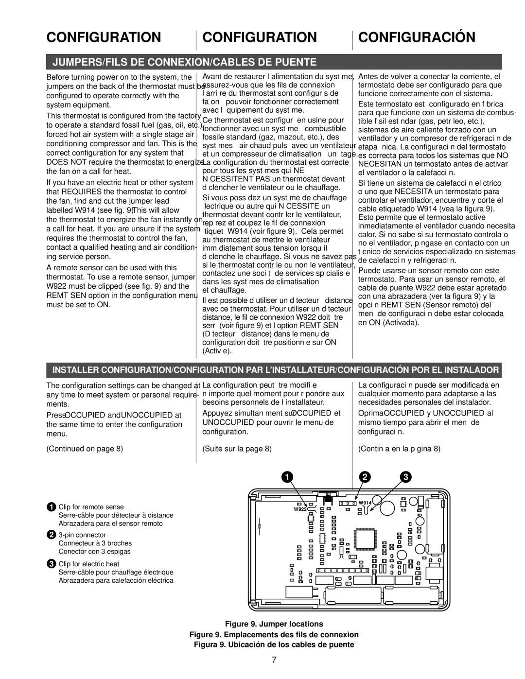
If you have an electric heat or other system that REQUIRES the thermostat to control the fan, find and cut the jumper lead labelled W914 (see fig. 9). This will allow the thermostat to energize the fan instantly on a call for heat. If you are unsure if the system requires the thermostat to control the fan, contact a qualified heating and air condition- ing service person.
A remote sensor can be used with this thermostat. To use a remote sensor, jumper W922 must be clipped (see fig. 9) and the REMT SEN option in the configuration menu must be set to ON.
Avant de restaurer l’alimentation du système,
Ce thermostat est configuré en usine pour fonctionner avec un système à combustible fossile standard (gaz, mazout, etc.), des systèmes à air chaud pulsé avec un ventilateur et un compresseur de climatisation à un étage. La configuration du thermostat est correcte pour tous les systèmes qui NE NÉCESSITENT PAS un thermostat devant déclencher le ventilateur ou le chauffage.
Si vous possédez un système de chauffage électrique ou autre qui NÉCESSITE un thermostat devant contrôler le ventilateur, repérez et coupez le fil de connexion étiqueté W914 (voir figure 9). Cela permet au thermostat de mettre le ventilateur immédiatement sous tension lorsqu’il déclenche le chauffage. Si vous ne savez pas si le thermostat contrôle ou non le ventilateur, contactez une société de services spécialisée dans les systèmes de climatisation
et chauffage.
Il est possible d’utiliser un détecteur à distance avec ce thermostat. Pour utiliser un détecteur à distance, le fil de connexion W922 doit être serré (voir figure 9) et l’option REMT SEN (Détecteur à distance) dans le menu de configuration doit être positionnée sur ON (Activée).
Antes de volver a conectar la corriente, el termostato debe ser configurado para que funcione correctamente con el sistema.
Este termostato está configurado en fábrica para que funcione con un sistema de combus- tible fósil estándar (gas, petróleo, etc.), sistemas de aire caliente forzado con un ventilador y un compresor de refrigeración de etapa única. La configuración del termostato es correcta para todos los sistemas que NO NECESITAN un termostato antes de activar el ventilador o la calefacción.
Si tiene un sistema de calefacción eléctrico o uno que NECESITA un termostato para controlar el ventilador, encuentre y corte el cable etiquetado W914 (vea la figura 9). Esto permite que el termostato active inmediatamente el ventilador cuando necesita calor. Si no sabe si su termostato controla o no el ventilador, póngase en contacto con un técnico de servicios especializado en sistemas de calefacción y refrigeración.
Puede usarse un sensor remoto con este termostato. Para usar un sensor remoto, el cable de puente W922 debe estar apretado con una abrazadera (ver la figura 9) y la opción REMT SEN (Sensor remoto) del menú de configuración debe estar colocada en ON (Activada).
INSTALLER CONFIGURATION/CONFIGURATION PAR L’INSTALLATEUR/CONFIGURACIÓN POR EL INSTALADOR
The configuration settings can be changed at any time to meet system or personal require- ments.
Press OCCUPIED and UNOCCUPIED at the same time to enter the configuration menu.
(Continued on page 8)
La configuration peut être modifiée à n’importe quel moment pour répondre aux besoins personnels de l’installateur.
Appuyez simultanément sur OCCUPIED et UNOCCUPIED pour ouvrir le menu de configuration.
(Suite sur la page 8)
1
La configuración puede ser modificada en cualquier momento para adaptarse a las necesidades personales del instalador.
Oprima OCCUPIED y UNOCCUPIED al mismo tiempo para abrir el menú de configuración.
(Continúa en la página 8)
2 3
1Clip for remote sense
2
3Clip for electric heat
W914
W922
Figure 9. Jumper locations
Figure 9. Emplacements des fils de connexion Figura 9. Ubicación de los cables de puente
7
