INSTALLATION
SYSTEM WIRING
REFERTOANDFOLLOWTHEAPPLIANCEMAN- UFACTURER’S WIRING DIAGRAM. REFER TO FIG. 4 AND 5 FOR TERMINAL IDENTIFICATION.
These valves are shipped with an external jumper installed for
•For
(see fig. 4 and 5).
•For proven/intermittent pilot gas applications such as intermittent pilot or
NOTE
All wiring should be installed in accordance with local and national electrical codes and ordinances.
Always check that the electrical power supply used agrees with the voltage and frequency shown on the gas control.
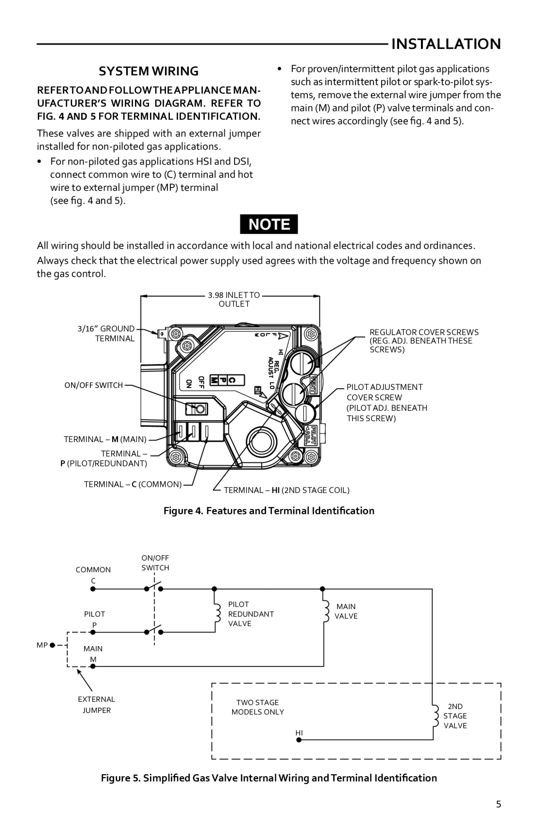
3/16” GROUND TERMINAL
3.98 INLET TO
OUTLET
REGULATOR COVER SCREWS (REG. ADJ. BENEATH THESE SCREWS)
ON/OFF SWITCH
TERMINAL – M (MAIN) ![]()
![]()
![]()
![]()
![]()
![]()
TERMINAL – P (PILOT/REDUNDANT)
TERMINAL – C (COMMON)
PILOT ADJUSTMENT COVER SCREW (PILOT ADJ. BENEATH THIS SCREW)
TERMINAL – HI (2ND STAGE COIL)
Figure 4. Features and Terminal Identification
ON/OFF
COMMON SWITCH
C
| PILOT | MAIN |
PILOT | REDUNDANT | VALVE |
P | VALVE |
|
MP | MAIN |
| |
| M |
EXTERNAL | TWO STAGE | 2ND | |
JUMPER | |||
MODELS ONLY | |||
STAGE | |||
|
| ||
|
| VALVE | |
|
| HI |
Figure 5. Simplified Gas Valve Internal Wiring and Terminal Identification
5