White Rodgers 37-6186B Programmable Cool Fan-Offand Fan-Ondelay, Programmable Heat Fan-Offdelay

Models: 37-6186B

1 8
Download 8 pages 5.18 Kb
Page 6
Image 6
PROGRAMMABLE COOL FAN-OFF AND FAN-ON DELAY.

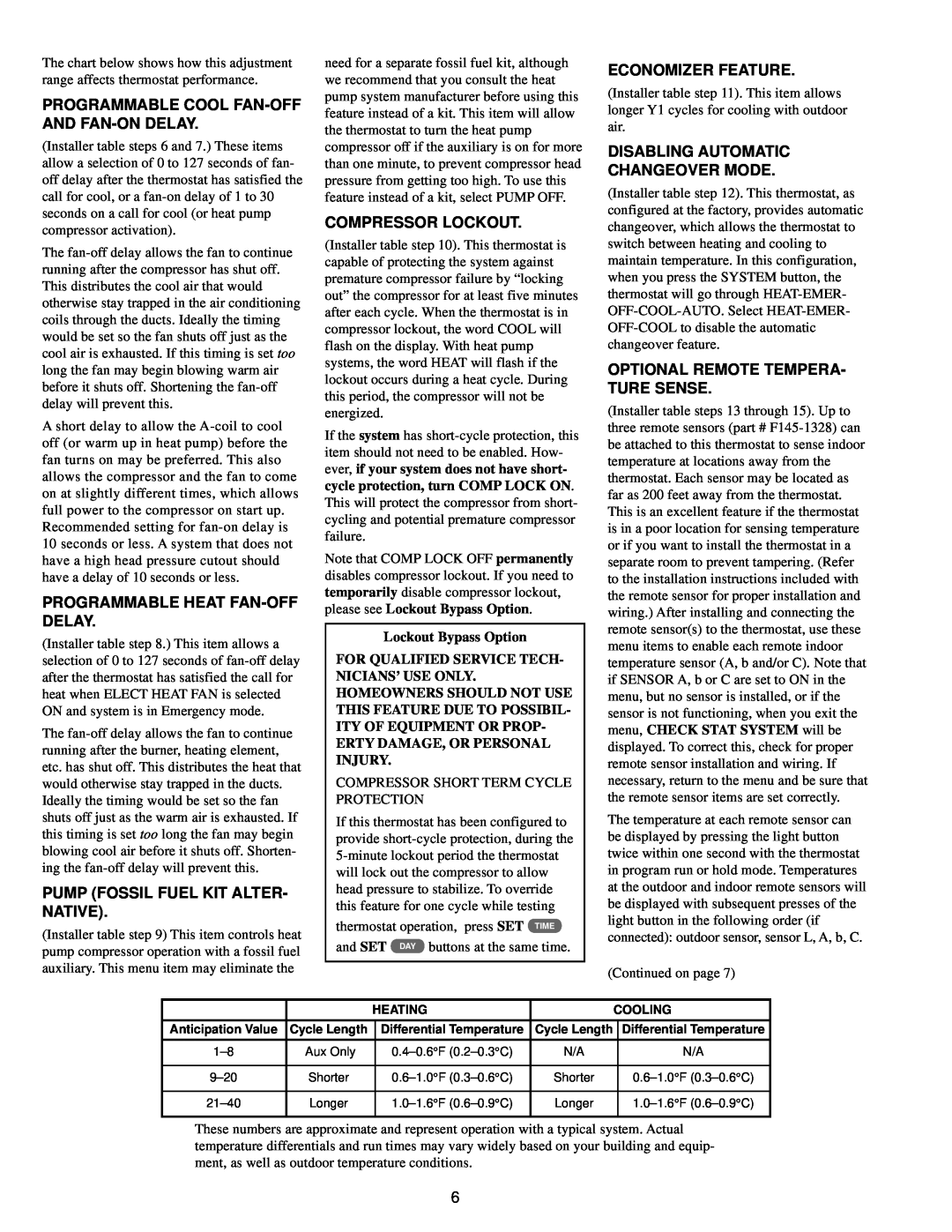
The chart below shows how this adjustment range affects thermostat performance.

PROGRAMMABLE COOL FAN-OFF AND FAN-ON DELAY.

(Installer table steps 6 and 7.) These items allow a selection of 0 to 127 seconds of fan- off delay after the thermostat has satisfied the call for cool, or a fan-on delay of 1 to 30 seconds on a call for cool (or heat pump compressor activation).

The fan-off delay allows the fan to continue running after the compressor has shut off. This distributes the cool air that would otherwise stay trapped in the air conditioning coils through the ducts. Ideally the timing would be set so the fan shuts off just as the cool air is exhausted. If this timing is set too long the fan may begin blowing warm air before it shuts off. Shortening the fan-off delay will prevent this.

A short delay to allow the A-coil to cool off (or warm up in heat pump) before the fan turns on may be preferred. This also allows the compressor and the fan to come on at slightly different times, which allows full power to the compressor on start up. Recommended setting for fan-on delay is 10 seconds or less. A system that does not have a high head pressure cutout should have a delay of 10 seconds or less.

PROGRAMMABLE HEAT FAN-OFF DELAY.

(Installer table step 8.) This item allows a selection of 0 to 127 seconds of fan-off delay after the thermostat has satisfied the call for heat when ELECT HEAT FAN is selected ON and system is in Emergency mode.

The fan-off delay allows the fan to continue running after the burner, heating element, etc. has shut off. This distributes the heat that would otherwise stay trapped in the ducts. Ideally the timing would be set so the fan shuts off just as the warm air is exhausted. If this timing is set too long the fan may begin blowing cool air before it shuts off. Shorten- ing the fan-off delay will prevent this.

PUMP (FOSSIL FUEL KIT ALTER- NATIVE).

(Installer table step 9) This item controls heat pump compressor operation with a fossil fuel auxiliary. This menu item may eliminate the

need for a separate fossil fuel kit, although we recommend that you consult the heat pump system manufacturer before using this feature instead of a kit. This item will allow the thermostat to turn the heat pump compressor off if the auxiliary is on for more than one minute, to prevent compressor head pressure from getting too high. To use this feature instead of a kit, select PUMP OFF.

COMPRESSOR LOCKOUT.

(Installer table step 10). This thermostat is capable of protecting the system against premature compressor failure by “locking out” the compressor for at least five minutes after each cycle. When the thermostat is in compressor lockout, the word COOL will flash on the display. With heat pump systems, the word HEAT will flash if the lockout occurs during a heat cycle. During this period, the compressor will not be energized.

If the system has short-cycle protection, this item should not need to be enabled. How- ever, if your system does not have short- cycle protection, turn COMP LOCK ON. This will protect the compressor from short- cycling and potential premature compressor failure.

Note that COMP LOCK OFF permanently disables compressor lockout. If you need to temporarily disable compressor lockout,

please see Lockout Bypass Option.

Lockout Bypass Option

FOR QUALIFIED SERVICE TECH- NICIANS’ USE ONLY. HOMEOWNERS SHOULD NOT USE THIS FEATURE DUE TO POSSIBIL- ITY OF EQUIPMENT OR PROP- ERTY DAMAGE, OR PERSONAL INJURY.

COMPRESSOR SHORT TERM CYCLE PROTECTION

If this thermostat has been configured to provide short-cycle protection, during the 5-minute lockout period the thermostat will lock out the compressor to allow head pressure to stabilize. To override this feature for one cycle while testing

thermostat operation, press SET TIME

and SET DAY buttons at the same time.

ECONOMIZER FEATURE.

(Installer table step 11). This item allows longer Y1 cycles for cooling with outdoor air.

DISABLING AUTOMATIC

CHANGEOVER MODE.

(Installer table step 12). This thermostat, as configured at the factory, provides automatic changeover, which allows the thermostat to switch between heating and cooling to maintain temperature. In this configuration, when you press the SYSTEM button, the thermostat will go through HEAT-EMER- OFF-COOL-AUTO. Select HEAT-EMER- OFF-COOL to disable the automatic changeover feature.

OPTIONAL REMOTE TEMPERA- TURE SENSE.

(Installer table steps 13 through 15). Up to three remote sensors (part # F145-1328) can be attached to this thermostat to sense indoor temperature at locations away from the thermostat. Each sensor may be located as far as 200 feet away from the thermostat. This is an excellent feature if the thermostat is in a poor location for sensing temperature or if you want to install the thermostat in a separate room to prevent tampering. (Refer to the installation instructions included with the remote sensor for proper installation and wiring.) After installing and connecting the remote sensor(s) to the thermostat, use these menu items to enable each remote indoor temperature sensor (A, b and/or C). Note that if SENSOR A, b or C are set to ON in the menu, but no sensor is installed, or if the sensor is not functioning, when you exit the menu, CHECK STAT SYSTEM will be displayed. To correct this, check for proper remote sensor installation and wiring. If necessary, return to the menu and be sure that the remote sensor items are set correctly.

The temperature at each remote sensor can be displayed by pressing the light button twice within one second with the thermostat in program run or hold mode. Temperatures at the outdoor and indoor remote sensors will be displayed with subsequent presses of the light button in the following order (if connected): outdoor sensor, sensor L, A, b, C.

(Continued on page 7)


HEATING


COOLING


Anticipation Value

Cycle Length


Differential Temperature

Cycle Length


Differential Temperature


1–8

Aux Only


0.4–0.6°F (0.2–0.3°C)

N/A


N/A


9–20

Shorter


0.6–1.0°F (0.3–0.6°C)

Shorter


0.6–1.0°F (0.3–0.6°C)


21–40

Longer


1.0–1.6°F (0.6–0.9°C)

Longer


1.0–1.6°F (0.6–0.9°C)


These numbers are approximate and represent operation with a typical system. Actual temperature differentials and run times may vary widely based on your building and equip- ment, as well as outdoor temperature conditions.

6

Page 6
Image 6
White Rodgers 37-6186B Programmable Cool Fan-Offand Fan-Ondelay, Programmable Heat Fan-Offdelay, Compressor Lockout