(Installer table step 16). If you wish to sense indoor temperature using ONLY the remote sensor(s), use this menu item to disable the temperature sensor in the thermostat (designated as the L sensor).
When operating with remote sensor(s), the thermostat will calculate an average of the sensed temperatures in all enabled sensor locations (A, B, C and/or L), then display the average temperature as the room tempera- ture. During programming, you can also assign each enabled sensor different priorities during different program periods. This allows the system to maintain a comfortable environment by giving higher priority to occupied locations. At the same time, efficient system operation is enhanced by giving lower priority to unoccupied locations. For detailed instructions on this feature, see the Operating Instructions.
OUTDOOR TEMPERATURE SENSE.
This thermostat can also display outdoor temperature, if you install an outdoor remote sensor with an outdoor temperature sensor probe
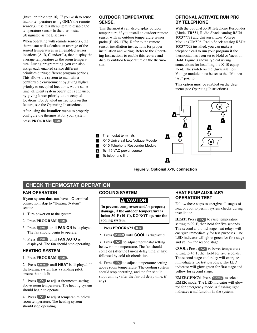
OPTIONAL ACTIVATE RUN PRG BY TELEPHONE
With the optional
This option must be enabled on the User menu (see Operating Instructions).
After using the Installer menu to properly configure the thermostat for your system,
press PROGRAM RUN .
4
PHR |
1 |
1Thermostat terminals
2
3
4To 115 VAC power source
5To telephone line
4
5
2
3
1 |
C |
Figure 3. Optional X-10 connection
CHECK THERMOSTAT OPERATION
FAN OPERATION
If your system does not have a G terminal connection, skip to “Heating System” section.
1.Turn power on to the system.
2.Press PROGRAM RUN .
3. | Press | FAN | until FAN ON is displayed. |
| The fan should begin to operate. | ||
4. | Press | FAN | until FAN AUTO is |
| displayed. The fan should stop operating. | ||
HEATING SYSTEM
1.Press PROGRAM RUN .
2.Press SYSTEM until HEAT is displayed. If the heating system has a standing pilot, ensure that it is lit.
3.Press ![]() to adjust thermostat setting above room temperature. The heating system
to adjust thermostat setting above room temperature. The heating system
should begin to operate.
4.Press ![]() to adjust temperature below room temperature. The heating system
to adjust temperature below room temperature. The heating system
should stop operating.
COOLING SYSTEM
!CAUTION
To prevent compressor and/or property damage, if the outdoor temperature is below 50°F (10°C), DO NOT operate the cooling system.
1.Press PROGRAM RUN .
2.Press SYSTEM until COOL is displayed.
3.Press ![]() to adjust thermostat setting below room temperature. The fan should
to adjust thermostat setting below room temperature. The fan should
come on (after the
4.Press ![]() to adjust temperature setting above room temperature. The cooling system
to adjust temperature setting above room temperature. The cooling system
should stop operating, and the fan should stop running (after the
HEAT PUMP AUXILIARY
OPERATION TEST
Follow these steps to energize all stages of heat or cool to permit system checks during installation.
HEAT: Press ![]() to raise temperature setting to 99°F, then hold for five seconds. The second and third stage heat relays will energize immediately for test purposes. The LED indicator will glow green for first stage and yellow for second stage.
to raise temperature setting to 99°F, then hold for five seconds. The second and third stage heat relays will energize immediately for test purposes. The LED indicator will glow green for first stage and yellow for second stage.
COOL: Press ![]() to lower temperature setting to 45°F, then hold for five seconds. The second stage cool relay will energize immediately for test purposes. The LED indicator will glow green for first stage and yellow for second stage.
to lower temperature setting to 45°F, then hold for five seconds. The second stage cool relay will energize immediately for test purposes. The LED indicator will glow green for first stage and yellow for second stage.
EMERGENCY: Press SYSTEM to select EMER mode. The LED indicator will glow red for emergency mode. A flashing light indicates a malfunction in the system.
7