CONFIGURATION
SWITCHES
RESET SWITCH
See the Troubleshooting section at the end of this document for more information about the function of this switch.
E2/P SWITCH
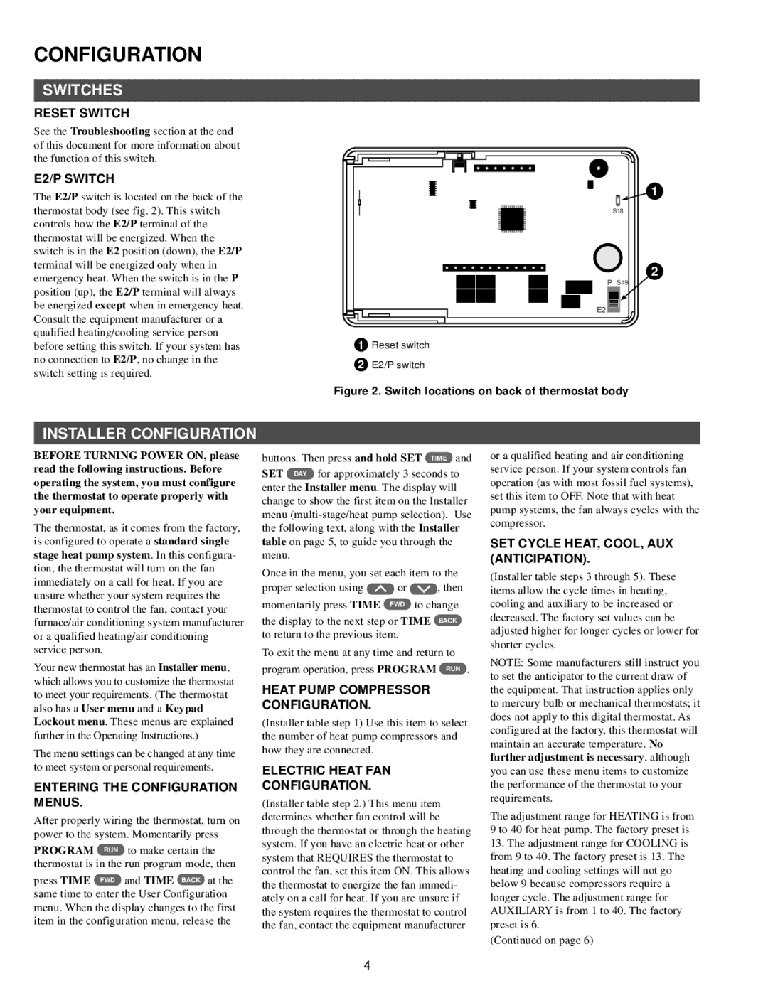
The E2/P switch is located on the back of the thermostat body (see fig. 2). This switch controls how the E2/P terminal of the thermostat will be energized. When the switch is in the E2 position (down), the E2/P terminal will be energized only when in emergency heat. When the switch is in the P position (up), the E2/P terminal will always be energized except when in emergency heat. Consult the equipment manufacturer or a qualified heating/cooling service person before setting this switch. If your system has no connection to E2/P, no change in the switch setting is required.
1
S18
2
P S19
E2
1Reset switch
2E2/P switch
Figure 2. Switch locations on back of thermostat body
INSTALLER CONFIGURATION
BEFORE TURNING POWER ON, please read the following instructions. Before operating the system, you must configure the thermostat to operate properly with your equipment.
The thermostat, as it comes from the factory, is configured to operate a standard single stage heat pump system. In this configura- tion, the thermostat will turn on the fan immediately on a call for heat. If you are unsure whether your system requires the thermostat to control the fan, contact your furnace/air conditioning system manufacturer or a qualified heating/air conditioning service person.
Your new thermostat has an Installer menu, which allows you to customize the thermostat to meet your requirements. (The thermostat also has a User menu and a Keypad Lockout menu. These menus are explained further in the Operating Instructions.)
The menu settings can be changed at any time to meet system or personal requirements.
ENTERING THE CONFIGURATION MENUS.
After properly wiring the thermostat, turn on power to the system. Momentarily press
PROGRAM RUN to make certain the thermostat is in the run program mode, then
press TIME FWD and TIME BACK at the same time to enter the User Configuration menu. When the display changes to the first item in the configuration menu, release the
buttons. Then press and hold SET TIME and SET DAY for approximately 3 seconds to enter the Installer menu. The display will change to show the first item on the Installer menu
Once in the menu, you set each item to the
proper selection using | or | , then |
momentarily press TIME | FWD | to change |
the display to the next step or TIME BACK to return to the previous item.
To exit the menu at any time and return to program operation, press PROGRAM RUN .
HEAT PUMP COMPRESSOR CONFIGURATION.
(Installer table step 1) Use this item to select the number of heat pump compressors and how they are connected.
ELECTRIC HEAT FAN
CONFIGURATION.
(Installer table step 2.) This menu item determines whether fan control will be through the thermostat or through the heating system. If you have an electric heat or other system that REQUIRES the thermostat to control the fan, set this item ON. This allows the thermostat to energize the fan immedi- ately on a call for heat. If you are unsure if the system requires the thermostat to control the fan, contact the equipment manufacturer
or a qualified heating and air conditioning service person. If your system controls fan operation (as with most fossil fuel systems), set this item to OFF. Note that with heat pump systems, the fan always cycles with the compressor.
SET CYCLE HEAT, COOL, AUX (ANTICIPATION).
(Installer table steps 3 through 5). These items allow the cycle times in heating, cooling and auxiliary to be increased or decreased. The factory set values can be adjusted higher for longer cycles or lower for shorter cycles.
NOTE: Some manufacturers still instruct you to set the anticipator to the current draw of the equipment. That instruction applies only to mercury bulb or mechanical thermostats; it does not apply to this digital thermostat. As configured at the factory, this thermostat will maintain an accurate temperature. No further adjustment is necessary, although you can use these menu items to customize the performance of the thermostat to your requirements.
The adjustment range for HEATING is from 9 to 40 for heat pump. The factory preset is
13.The adjustment range for COOLING is from 9 to 40. The factory preset is 13. The heating and cooling settings will not go below 9 because compressors require a longer cycle. The adjustment range for AUXILIARY is from 1 to 40. The factory preset is 6.
(Continued on page 6)
4