Installation and Assembly
Tools required for assembly:
Forklift or hoist with slings
16mm
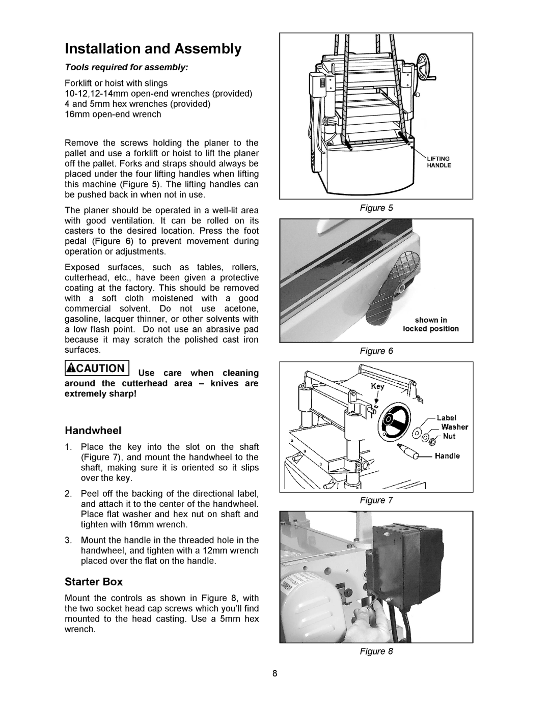
Remove the screws holding the planer to the pallet and use a forklift or hoist to lift the planer off the pallet. Forks and straps should always be placed under the four lifting handles when lifting this machine (Figure 5). The lifting handles can be pushed back in when not in use.
The planer should be operated in a
Exposed surfaces, such as tables, rollers, cutterhead, etc., have been given a protective coating at the factory. This should be removed with a soft cloth moistened with a good commercial solvent. Do not use acetone, gasoline, lacquer thinner, or other solvents with a low flash point. Do not use an abrasive pad because it may scratch the polished cast iron surfaces.
![]() Use care when cleaning around the cutterhead area – knives are extremely sharp!
Use care when cleaning around the cutterhead area – knives are extremely sharp!
Handwheel
1.Place the key into the slot on the shaft (Figure 7), and mount the handwheel to the shaft, making sure it is oriented so it slips over the key.
2.Peel off the backing of the directional label, and attach it to the center of the handwheel. Place flat washer and hex nut on shaft and tighten with 16mm wrench.
3.Mount the handle in the threaded hole in the handwheel, and tighten with a 12mm wrench placed over the flat on the handle.
Starter Box
Mount the controls as shown in Figure 8, with the two socket head cap screws which you’ll find mounted to the head casting. Use a 5mm hex wrench.
Figure 5
Figure 6
Figure 7
Figure 8
8