Air Cushioned Dead Head Assembly
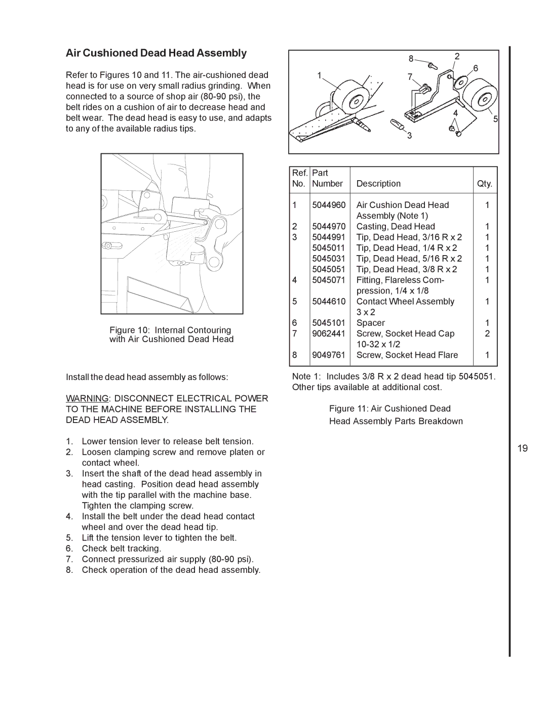
Refer to Figures 10 and 11. The
Figure 10: Internal Contouring with Air Cushioned Dead Head
Install the dead head assembly as follows:
WARNING: DISCONNECT ELECTRICAL POWER TO THE MACHINE BEFORE INSTALLING THE DEAD HEAD ASSEMBLY.
1.Lower tension lever to release belt tension.
2.Loosen clamping screw and remove platen or contact wheel.
3.Insert the shaft of the dead head assembly in head casting. Position dead head assembly with the tip parallel with the machine base.
Tighten the clamping screw.
4.Install the belt under the dead head contact wheel and over the dead head tip.
5.Lift the tension lever to tighten the belt.
6.Check belt tracking.
7.Connect pressurized air supply (80-90 psi).
8.Check operation of the dead head assembly.
|
| 8 | 2 | 6 |
| 1 | 7 |
| |
|
|
| ||
|
| 4 | 5 | |
|
|
|
| |
|
| 3 |
|
|
|
|
|
|
|
|
|
|
|
|
Ref. | Part |
|
|
|
No. | Number | Description |
| Qty. |
|
|
|
|
|
1 | 5044960 | Air Cushion Dead Head |
| 1 |
|
| Assembly (Note 1) |
|
|
2 | 5044970 | Casting, Dead Head |
| 1 |
3 | 5044991 | Tip, Dead Head, 3/16 R x 2 | 1 | |
| 5045011 | Tip, Dead Head, 1/4 R x 2 | 1 | |
| 5045031 | Tip, Dead Head, 5/16 R x 2 | 1 | |
| 5045051 | Tip, Dead Head, 3/8 R x 2 | 1 | |
4 | 5045071 | Fitting, Flareless Com- |
| 1 |
|
| pression, 1/4 x 1/8 |
|
|
5 | 5044610 | Contact Wheel Assembly |
| 1 |
|
| 3 x 2 |
|
|
6 | 5045101 | Spacer |
| 1 |
7 | 9062441 | Screw, Socket Head Cap |
| 2 |
|
|
|
| |
8 | 9049761 | Screw, Socket Head Flare | 1 | |
|
|
|
|
|
Note 1: Includes 3/8 R x 2 dead head tip 5045051. Other tips available at additional cost.
Figure 11: Air Cushioned Dead
Head Assembly Parts Breakdown
19
