RM-9947, RM-9946 specifications
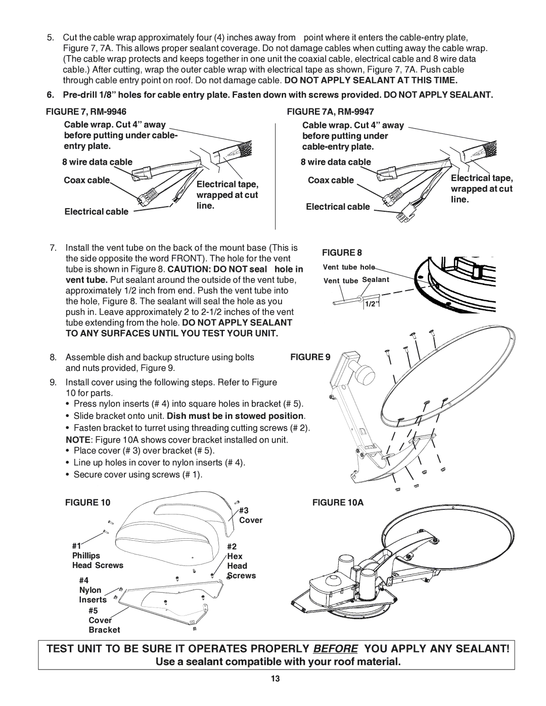
The Winegard RM-9946 and RM-9947 are advanced mobile satellite antennas designed to enhance the reception of satellite television signals, particularly for RVers, boaters, and outdoor enthusiasts. These streamlined models are engineered to provide robust performance, ensuring that users have access to their favorite channels no matter where their adventures take them.One of the standout features of both the RM-9946 and RM-9947 is their automatic satellite acquisition capability. Upon startup, these antennas quickly lock onto satellite signals without the need for manual adjustments, making it incredibly convenient for those on the go. This feature is essential for users who want uninterrupted viewing while traveling, as it minimizes setup time and maximizes entertainment.
Both models utilize advanced multi-satellite capabilities, allowing users to access a broader range of programming options from various satellite providers. This flexibility means that whether you’re a fan of regional sports networks or national broadcasters, you are more likely to find your preferred channels. The antennas are built with high-quality materials to endure the rigors of travel and exposure to the elements, ensuring long-term durability.
The RM-9946 and RM-9947 also incorporate state-of-the-art tracking technology. As you move, these antennas continuously adjust to maintain a strong signal, which significantly reduces interruptions during inclement weather or when navigating through areas with challenging satellite line-of-sight.
Another notable characteristic of these antennas is their sleek, low-profile design. This aesthetic advantage not only enhances the visual appeal of your vehicle but also helps to reduce wind resistance and noise, which can affect fuel efficiency and overall travel experience.
Installation is straightforward, with user-friendly mounting options provided in the package. Both antennas are designed to be easily integrated with standard receivers and satellite dishes, making them an ideal choice for those looking to upgrade their existing setup or establish a new one.
In conclusion, the Winegard RM-9946 and RM-9947 are exemplary choices for anyone seeking a reliable, efficient, and user-friendly mobile satellite solution. With features like automatic satellite acquisition, multi-satellite capabilities, durable construction, and advanced tracking technology, these antennas are poised to deliver a superior viewing experience in any outdoor environment. Whether you’re camping, tailgating, or cruising along the coast, Winegard’s innovative design ensures that you never miss a moment of your favorite programming.

