Torque Mounting Hardware | NOTICE |
■ Check torque value of mount hardware after 10 hours of operation and again after every 50 hours of operation.
| TORQUE SPECIFICATIONS |
| ||
|
|
| Wrench |
|
Ref | Cap Screw | Qty | Size | Required Torque |
20 | M16 x 2.0P x 40 mm FHCS CL10.9 | 2 | 24 mm | 173 |
24 | M16 x 2.0P x 55 mm CL8.8 | 2 | 24 mm | 125 |
25 | M16 x 2.0P x 70 mm CL8.8 | 2 | 24 mm | 125 |
26 | 1/2 NC x 2 GR5 | 16 | 3/4" | 85 |
30 | M12 x 1.75P x 150 mm CL8.8 | 4 | 18 mm | 50 |
32 | 5/8 NC x 2 GR5 | 14 | 15/16" | 170 |
|
|
|
|
|
Attach Backhoe Mounts to Backhoe
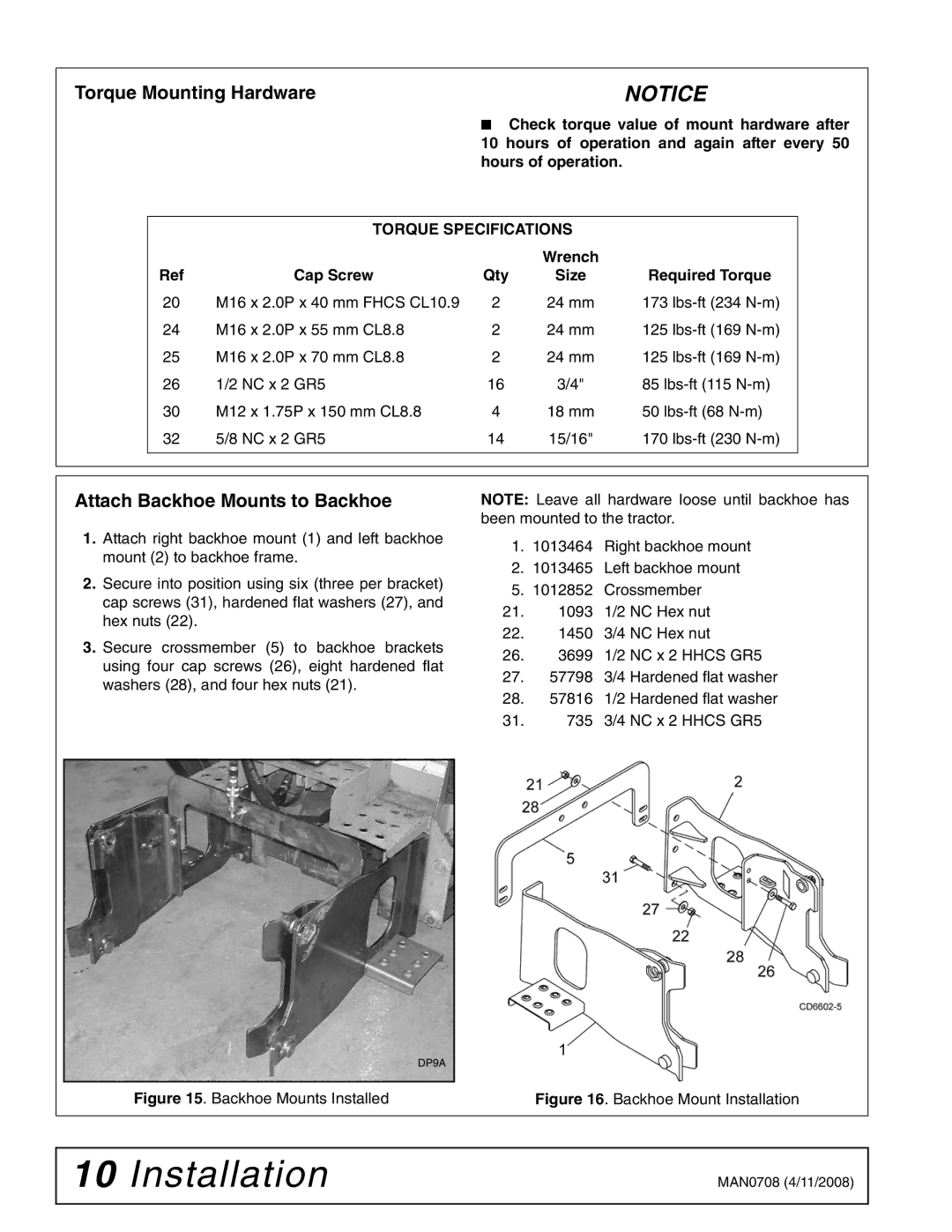
1.Attach right backhoe mount (1) and left backhoe mount (2) to backhoe frame.
2.Secure into position using six (three per bracket) cap screws (31), hardened flat washers (27), and hex nuts (22).
3.Secure crossmember (5) to backhoe brackets using four cap screws (26), eight hardened flat washers (28), and four hex nuts (21).
NOTE: Leave all hardware loose until backhoe has been mounted to the tractor.
1.1013464 Right backhoe mount
2.1013465 Left backhoe mount
5.1012852 Crossmember
21.1093 1/2 NC Hex nut
22.1450 3/4 NC Hex nut
26.3699 1/2 NC x 2 HHCS GR5
27.57798 3/4 Hardened flat washer
28.57816 1/2 Hardened flat washer
31. 735 3/4 NC x 2 HHCS GR5
| DP9A |
Figure 15. Backhoe Mounts Installed | Figure 16. Backhoe Mount Installation |
10 Installation | MAN0708 (4/11/2008) |
|
|
