CROSSBAR INSTALLATION
1.Using emery cloth (220 or finer), remove surface rust, Loctite® and foreign material from hub, splined gearbox vertical shaft, and crossbar assembly.
2.Slide crossbar assembly (10) onto splined shaft. Install nut (86) and align a slot with hole in splined shaft. Torque nut to 450
3.Install cotter pin (85) through slot in nut and bend ends over.
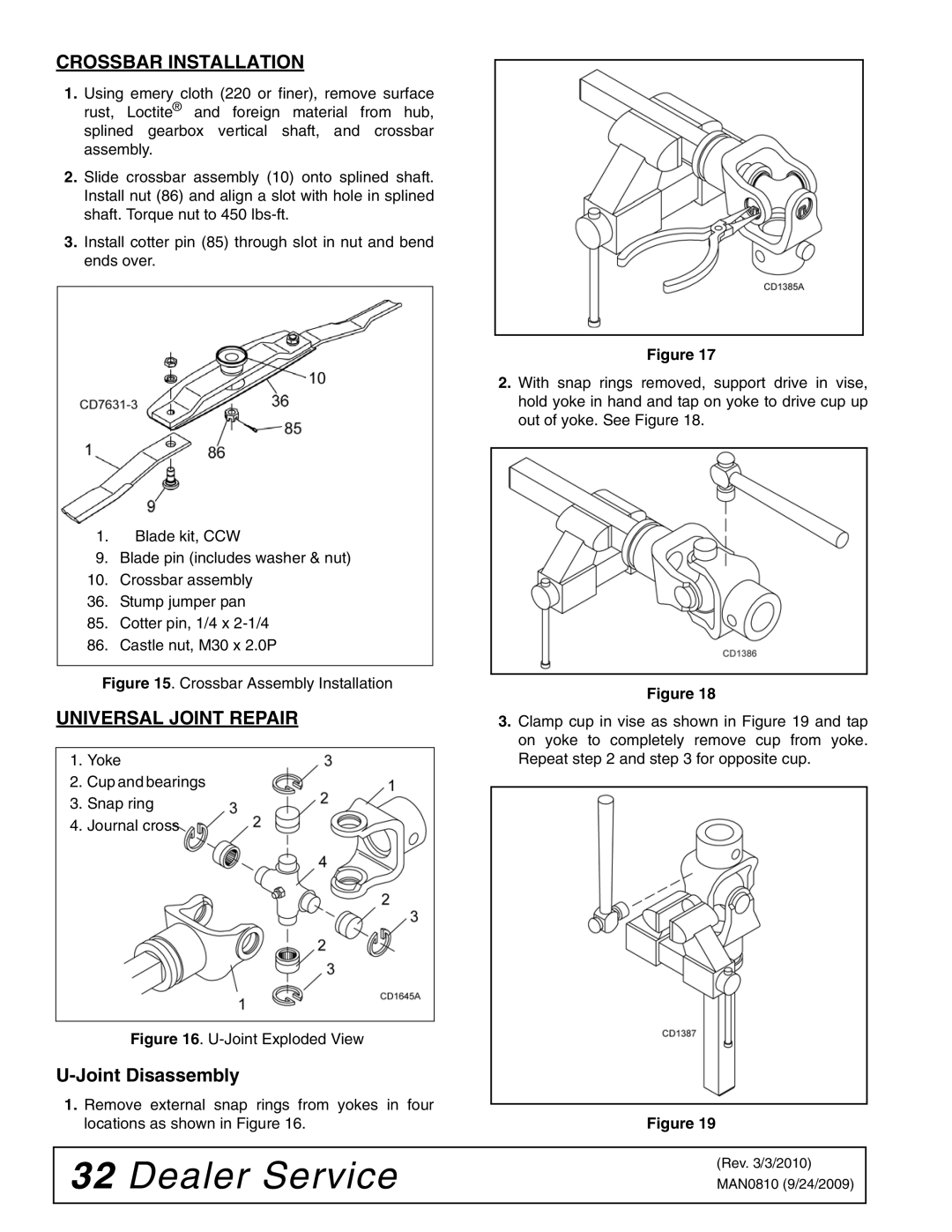
1.Blade kit, CCW
9.Blade pin (includes washer & nut)
10.Crossbar assembly
36.Stump jumper pan
85.Cotter pin, 1/4 x
86.Castle nut, M30 x 2.0P
Figure 15. Crossbar Assembly Installation
UNIVERSAL JOINT REPAIR
1.Yoke
2.Cup and bearings
3.Snap ring
4.Journal cross
Figure 16. U-Joint Exploded View
U-Joint Disassembly
1.Remove external snap rings from yokes in four locations as shown in Figure 16.
Figure 17
2.With snap rings removed, support drive in vise, hold yoke in hand and tap on yoke to drive cup up out of yoke. See Figure 18.
Figure 18
3.Clamp cup in vise as shown in Figure 19 and tap on yoke to completely remove cup from yoke. Repeat step 2 and step 3 for opposite cup.
Figure 19
32 Dealer Service
(Rev. 3/3/2010)
MAN0810 (9/24/2009)