Install CV Drive
1.Align hole in drive yoke with groove on gearbox input shaft and slide rear half of drive (5) onto shaft.
2.Secure with bolt and nut supplied with drive.
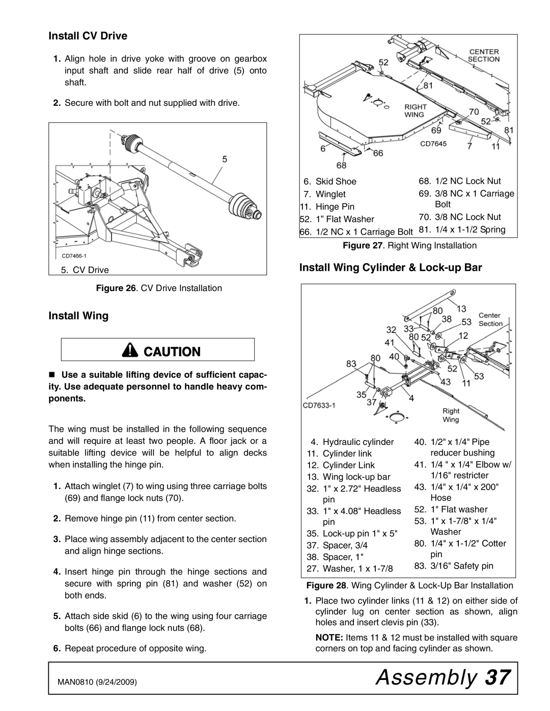
5. CV Drive
Figure 26. CV Drive Installation
Install Wing
![]() CAUTION
CAUTION
Use a suitable lifting device of sufficient capac- ity. Use adequate personnel to handle heavy com- ponents.
The wing must be installed in the following sequence and will require at least two people. A floor jack or a suitable lifting device will be helpful to align decks when installing the hinge pin.
1.Attach winglet (7) to wing using three carriage bolts (69) and flange lock nuts (70).
2.Remove hinge pin (11) from center section.
3.Place wing assembly adjacent to the center section and align hinge sections.
4.Insert hinge pin through the hinge sections and secure with spring pin (81) and washer (52) on both ends.
5.Attach side skid (6) to the wing using four carriage bolts (66) and flange lock nuts (68).
6.Repeat procedure of opposite wing.
6. | Skid Shoe | 68. | 1/2 NC Lock Nut |
7. | Winglet | 69. | 3/8 NC x 1 Carriage |
11. | Hinge Pin |
| Bolt |
52. | 1” Flat Washer | 70. | 3/8 NC Lock Nut |
66.1/2 NC x 1 Carriage Bolt 81. 1/4 x
Install Wing Cylinder & Lock-up Bar
4. | Hydraulic cylinder | 40. | 1/2" x 1/4" Pipe |
| |
11. | Cylinder link |
| reducer bushing | ||
12. | Cylinder Link | 41. | 1/4 " x 1/4" Elbow w/ | ||
13. | Wing |
| 1/16" restricter | ||
32. | 1" x 2.72" Headless | 43. | 1/4" x 1/4" x 200" | ||
| pin |
| Hose | ||
33. | 1" x 4.08" Headless | 52. | 1" Flat washer | ||
| pin | 53. | 1" x | ||
35. |
| Washer | |||
37. | Spacer, 3/4 | 80. | 1/4" x | ||
38. | Spacer, 1" |
| pin | ||
83. | 3/16" Safety pin | ||||
27. | Washer, 1 x | ||||
|
|
| |||
Figure 28. Wing Cylinder & Lock-Up Bar Installation
1.Place two cylinder links (11 & 12) on either side of cylinder lug on center section as shown, align holes and insert clevis pin (33).
NOTE: Items 11 & 12 must be installed with square corners on top and facing cylinder as shown.
MAN0810 (9/24/2009) | Assembly 37 |
|
|