Blade Spindle Assembly (Figure 13)
Bearing cones and cups are designed to work together. It is important to position them so bearing cone taper mates with cup taper.
Lubricate new cups with a light oil. Place them in spin- dle housing so they will mate with bearing cones. Cups and cones are a press fit to minimize wear.
Seat cups securely with a press or place a large drift in the flat lip and drive cups into housing until they seat against machined shoulder of housing.
Place bottom bearing cone onto spindle shaft with taper positioned to mate with cup. Press onto shaft and seat on bottom shoulder of shaft.
Insert shaft and bearing through bottom of housing.
Fill housing cavity with a medium grade grease.
Install top bearing on shaft to mate with top cone.
Apply a thin coat of Permatex to shaft area where sleeve will seat. Install sleeve on shaft and press sleeve and bearing into housing until all free play is removed and there is a very light drag on bearings (similar to adjusting front wheel bearings on an auto- mobile). Check by spinning spindle. It should turn freely.
Be careful not to overtighten bearings. Proper bearing adjustment is essential to good bearing life. Should you overtighten bearings, hold spindle housing and rap spindle shaft with a lead hammer.
Place a rag over bearings to protect them and drill a 3/16" hole 9/32" down from top of sleeve and drive roll pin through sleeve and shaft to hold bearing adjust- ment. Make sure roll pin does not extend past outer diameter of sleeve on either side.
NOTICE
■Improper positioning of seals can cause seal damage.
Proper seal installation is important. An improperly installed seal will leak and could cause bearing failure.
Pull the rubber portion of seal back and locate spring. Lightly coat area of housing where seals seat with Per- matex. Install bottom seal with spring up toward center of housing.
Place seal squarely on housing and select a piece of pipe or tubing with an OD that will set on outside edge
of seal. A tubing with an OD that is too small will bow seal cage.
Carefully press seal into housing, preventing distortion to metal seal cage. Seal should seat firmly and squarely against machined shoulder in housing.
Make sure seal lip did not roll under. Distortion to seal cage or damage to seal lip will cause seal to leak. Damaged seals must be replaced.
Carefully press top seal in with spring up away from center of housing. Top seal should be flush with, to 1/16" above, housing.
Lubricate spindle with a medium grade grease. Rotate housing on spindle shaft, checking for free movement.
Blade Spindle Installation
Install spindle through bottom of mower and install four mounting bolts. Be sure to position grease fittings toward lubrication access areas.
Blade Spindle Pulley Installation
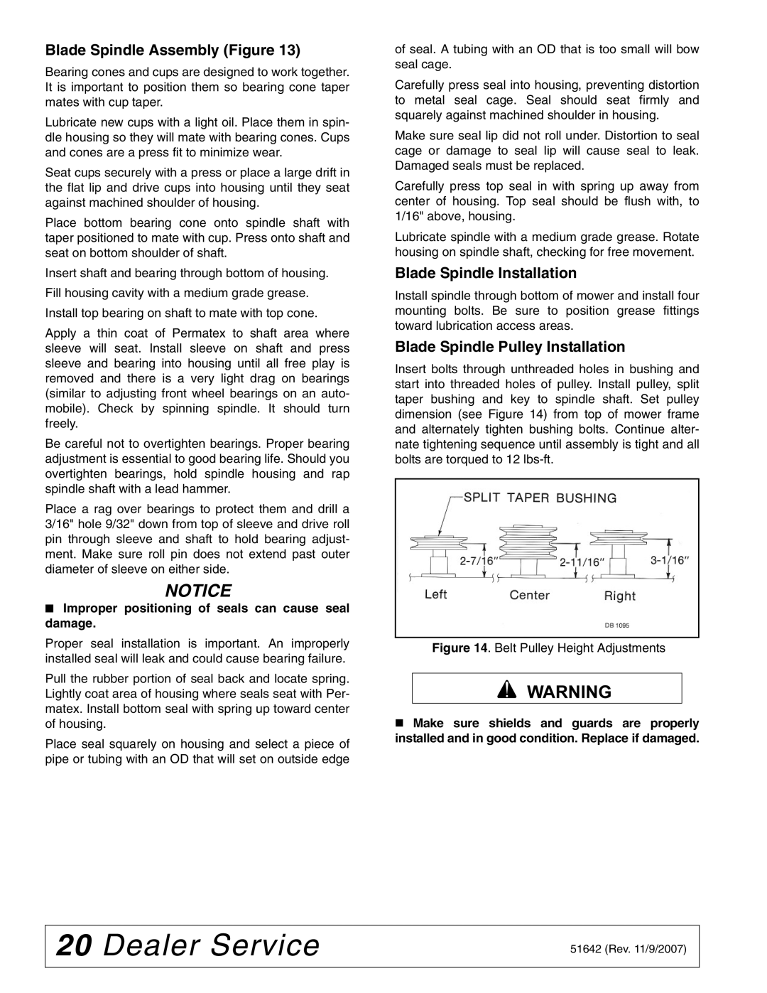
Insert bolts through unthreaded holes in bushing and start into threaded holes of pulley. Install pulley, split taper bushing and key to spindle shaft. Set pulley dimension (see Figure 14) from top of mower frame and alternately tighten bushing bolts. Continue alter- nate tightening sequence until assembly is tight and all bolts are torqued to 12
Figure 14. Belt Pulley Height Adjustments
Make sure shields and guards are properly installed and in good condition. Replace if damaged.
20 Dealer Service | 51642 (Rev. 11/9/2007) |
|