INSTALL SMV SIGN
1.Attach SMV (Slow Moving Vehicle) socket (93) to SMV emblem bracket (71) using two carriage bolts (97) and lock nuts (30). See Figure 18 and Figure 19.
2.Attach SMV sign (98) to SMV bracket (94) using two cap screws (95) and lock nuts (96).
3.Insert SMV sign into socket.
Figure 18. SMV Socket Installed
| 98 |
|
| 95 | 96 |
|
| |
| 94 |
|
| 97 | 93 |
| 71 |
|
30 | ||
| ||
30. | 5/16 NC Lock nut |
|
71. | SMV Emblem bracket |
|
93. | SMV Socket |
|
94. | SMV Bracket |
|
95. | 1/4 NC x 3/4 Cap screw |
|
96. | 1/4 NC Nylock nut |
|
97. | 5/16 NC x 3/4 Carriage bolt |
|
98. | SMV Sign |
|
Figure 19. SMV Sign Installation
INSTALL DISCHARGE TUBE (OPTIONAL)
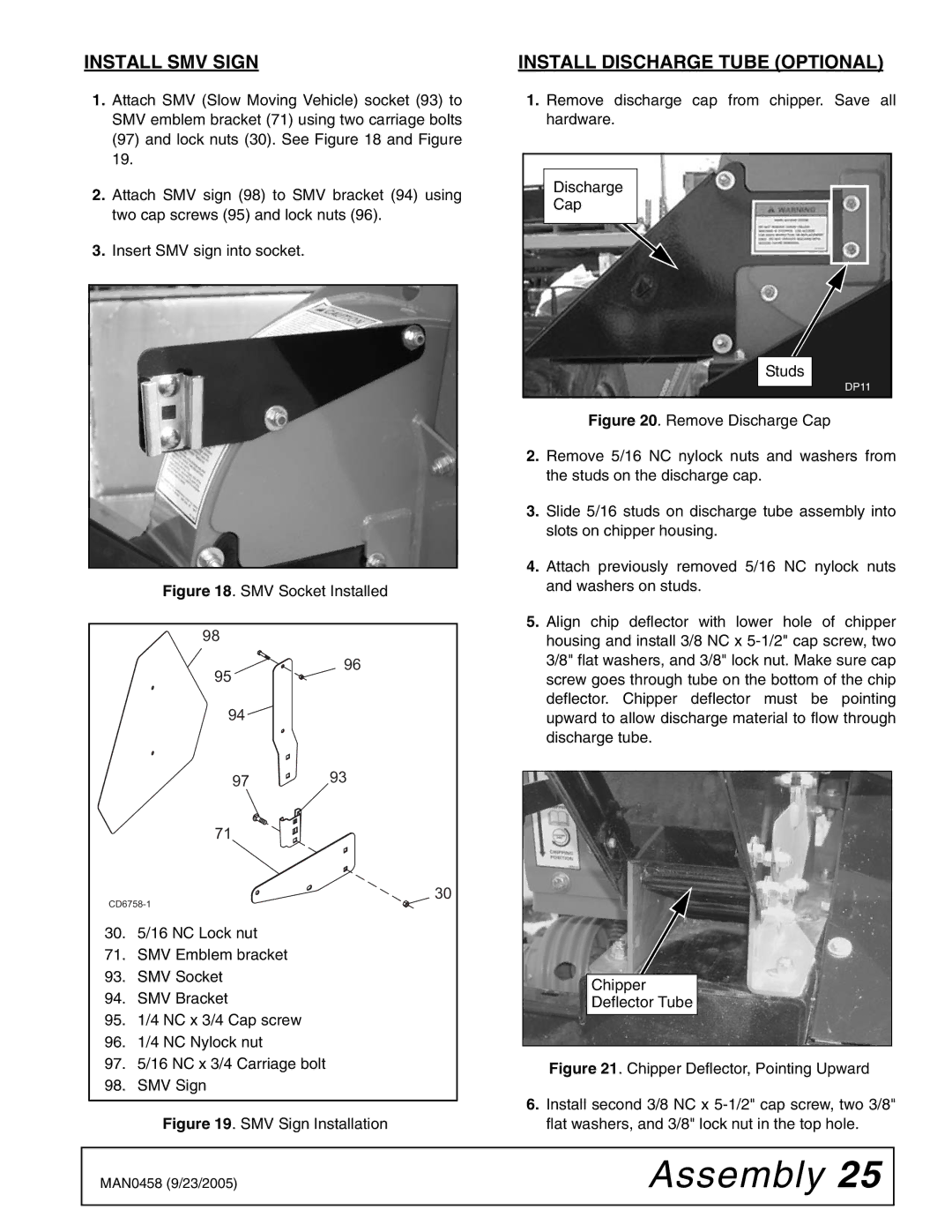
1.Remove discharge cap from chipper. Save all hardware.
Discharge
Cap
Studs
DP11
Figure 20. Remove Discharge Cap
2.Remove 5/16 NC nylock nuts and washers from the studs on the discharge cap.
3.Slide 5/16 studs on discharge tube assembly into slots on chipper housing.
4.Attach previously removed 5/16 NC nylock nuts and washers on studs.
5.Align chip deflector with lower hole of chipper housing and install 3/8 NC x 5-1/2" cap screw, two 3/8" flat washers, and 3/8" lock nut. Make sure cap screw goes through tube on the bottom of the chip deflector. Chipper deflector must be pointing upward to allow discharge material to flow through discharge tube.
Chipper
Deflector Tube
Figure 21. Chipper Deflector, Pointing Upward
6.Install second 3/8 NC x 5-1/2" cap screw, two 3/8" flat washers, and 3/8" lock nut in the top hole.
MAN0458 (9/23/2005) | Assembly 25 |
|
|