Installation
Cabling Procedure
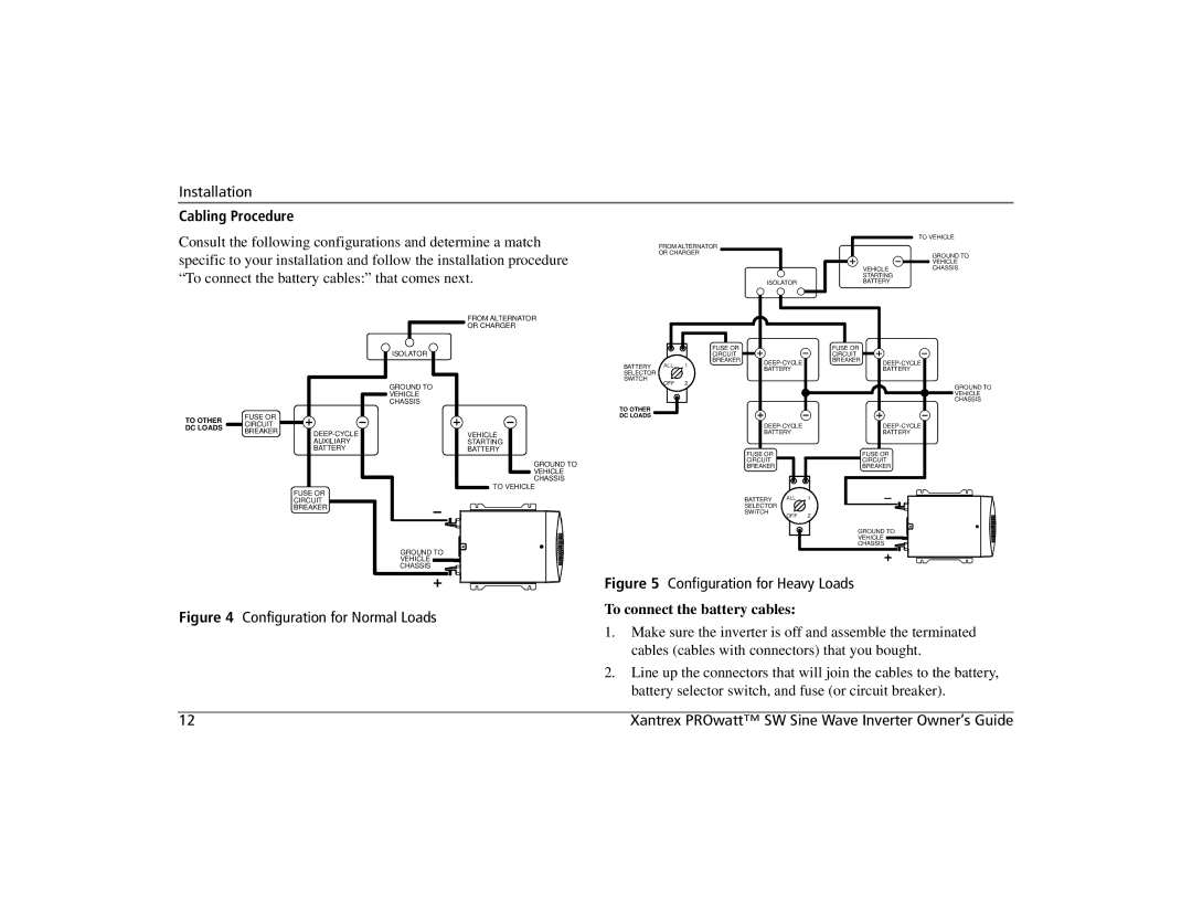
Consult the following configurations and determine a match specific to your installation and follow the installation procedure “To connect the battery cables:” that comes next.
|
| TO VEHICLE |
FROM ALTERNATOR |
|
|
OR CHARGER |
| GROUND TO |
|
| VEHICLE |
| VEHICLE | CHASSIS |
| STARTING |
|
ISOLATOR | BATTERY |
|
TO OTHER DC LOADS
| ISOLATOR |
| GROUND TO |
| VEHICLE |
| CHASSIS |
FUSE OR |
|
CIRCUIT |
|
BREAKER | |
| AUXILIARY |
| BATTERY |
| FUSE OR |
| CIRCUIT |
| BREAKER |
GROUND TO
VEHICLE
CHASSIS
FROM ALTERNATOR
OR CHARGER
VEHICLE
STARTING
BATTERY
GROUND TO
![]()
![]() VEHICLE CHASSIS
VEHICLE CHASSIS
![]()
![]() TO VEHICLE
TO VEHICLE
|
|
| FUSE OR |
| FUSE OR |
|
|
|
| CIRCUIT |
| CIRCUIT |
|
BATTERY | ALL | 1 | BREAKER | BREAKER | ||
| BATTERY |
| BATTERY | |||
SELECTOR |
|
|
|
| ||
|
|
|
|
|
| |
SWITCH | OFF | 2 |
|
|
|
|
|
|
|
|
|
TO OTHER
DC LOADS
BATTERY | BATTERY |
FUSE OR |
| FUSE OR |
CIRCUIT |
| CIRCUIT |
BREAKER |
| BREAKER |
BATTERY | ALL | 1 |
SELECTOR |
|
|
SWITCH | OFF | 2 |
| ||
|
| GROUND TO |
|
| VEHICLE |
|
| CHASSIS |
GROUND TO ![]() VEHICLE
VEHICLE
CHASSIS
|
|
|
| Figure 5 Configuration for Heavy Loads | ||
|
|
|
| |||
Figure 4 Configuration for Normal Loads |
| To connect the battery cables: | ||||
1. | Make sure the inverter is off and assemble the terminated | |||||
|
|
| ||||
|
|
|
|
| cables (cables with connectors) that you bought. | |
|
|
| 2. | Line up the connectors that will join the cables to the battery, | ||
|
|
|
|
| battery selector switch, and fuse (or circuit breaker). | |
|
|
|
|
|
| |
12 |
|
|
|
| Xantrex PROwatt™ SW Sine Wave Inverter Owner’s Guide | |