SECTION I – GENERAL DESCRIPTION
1-1.GENERAL.Yale “Global King” electric hoists are wire rope and drum type hoists that are manufactured with an integral trolley. These hoists are all low headroom models with the drum and upper block (or dead-end anchor depending on the reeving type) on opposite sides of the beam suspending the trolley. There are two basic frame sizes each with two standard lifts: the “B” Frame handles capacities up to 5 tonne; and the “C” Frame handles capacities up to 10 tonne. The “B” Frame has an integral trolley with two different flange width ranges available: 4-5/8” through 14” or 14-1/8” through 20” wide with a maximum flange thickness of 1-3/4”. The “C” Frame integral trolley has a flange range of 4 5/8” through 20” with a maximum flange thickness of 2”. The hoist motor is 2-speed with a 6:1 ratio between high and low speeds as standard. The Motor Driven trolley has two available speeds with 1- speed, 2-speed, or Variable Frequency control.
Throughout this manual you will see references to the “B” or “C” frame hoists. If you are unsure about which frame size you have, see Section IV, Paragraph 4-2 for a simple gearcase measurement to easily determine the size of your hoist.
1-2.BASIC CONSTRUCTION. Yale “Global King” hoists consist of a rugged steel frame which houses a lifting drum and serves as the suspension for carrying the entire hoist load. An aluminum gearcase, attached to one end of the drum frame, houses a triple-reduction gear train. The first two reductions are helical with the third being spur. Attached to the gearcase is a 2-speed hoisting motor with a 6:1 ratio between the high and low speeds. A 200% torque DC motor brake is attached to the motor. A single NEMA 4/12 control enclosure contains both the hoist and trolley electrical system controls. Hoisting cable and a covered lower block assembly are used for lifting loads. A rotary geared limit switch is used to limit travel both up and down. A secondary block operated limit switch is used to limit the travel of the lower block when raising. A push button control station (purchased separately) for operating the hoist is suspended on a wire strain cable attached to the hoist.
SECTION II – INSTALLATION
 WARNING
Only qualified personnel properly supervised shall mount the hoist and trolley on the monorail and perform final pre-operation inspection.
2-1.GENERAL.Yale “Global King” electric hoists are lubricated and tested before being shipped from the factory. To place a hoist in service, adjust appropriately for the beam flange width (Paragraph 2-2), connect to electrical service (Paragraph 2-3) and perform pre-operation tests and checks (Paragraph 2-4).
 WARNING
Working in or near exposed energized electrical equipment presents the danger of electric shock.
TO AVOID INJURY:
DISCONNECT POWER AND IMPLEMENT LOCKOUT/TAGOUT PROCEDURE BEFORE REMOVING COVER OR SERVICING THIS EQUIPMENT.
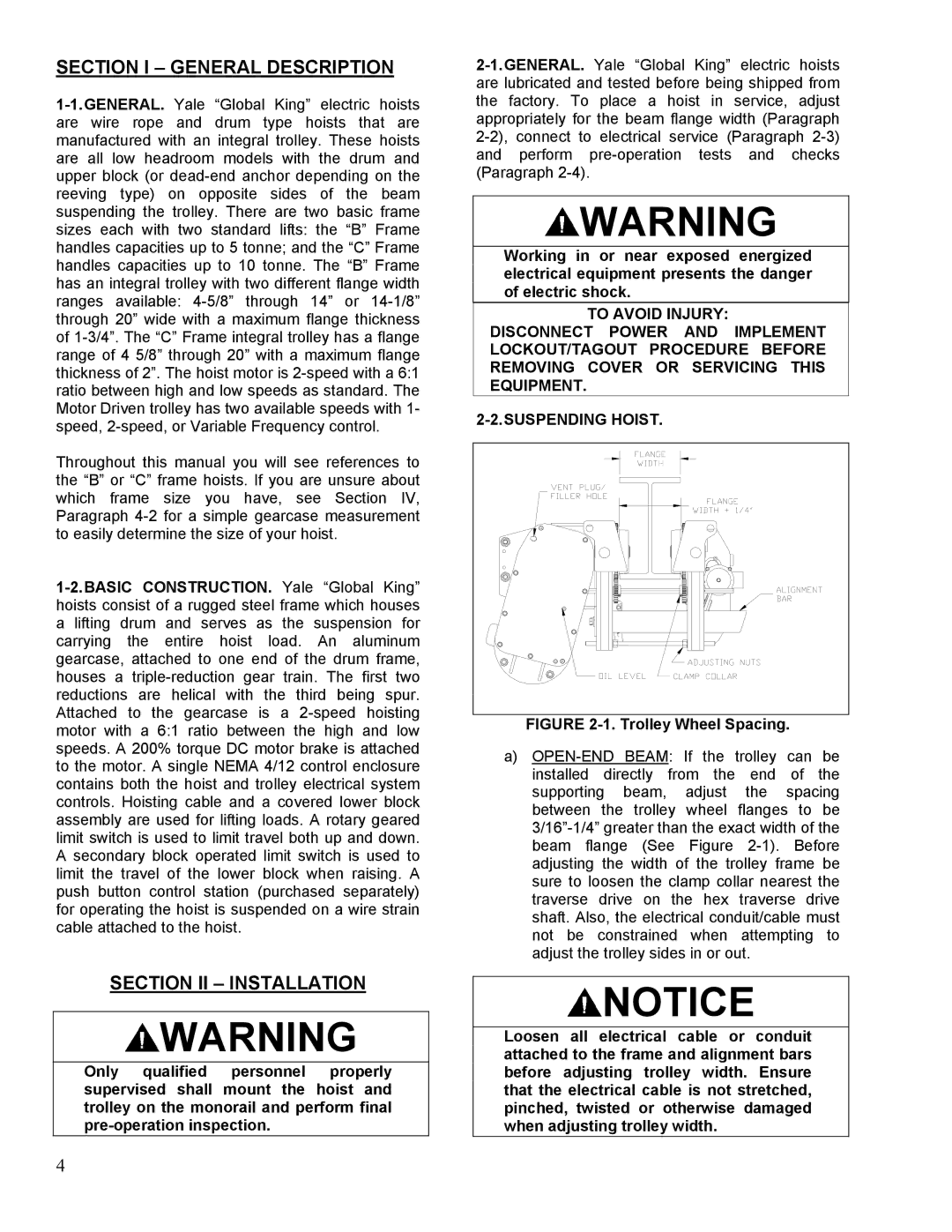
FIGURE 2-1. Trolley Wheel Spacing.
a)OPEN-END BEAM: If the trolley can be installed directly from the end of the supporting beam, adjust the spacing between the trolley wheel flanges to be 3/16”-1/4” greater than the exact width of the beam flange (See Figure 2-1). Before adjusting the width of the trolley frame be sure to loosen the clamp collar nearest the traverse drive on the hex traverse drive shaft. Also, the electrical conduit/cable must not be constrained when attempting to adjust the trolley sides in or out.
 NOTICE
Loosen all electrical cable or conduit attached to the frame and alignment bars before adjusting trolley width. Ensure that the electrical cable is not stretched, pinched, twisted or otherwise damaged when adjusting trolley width.