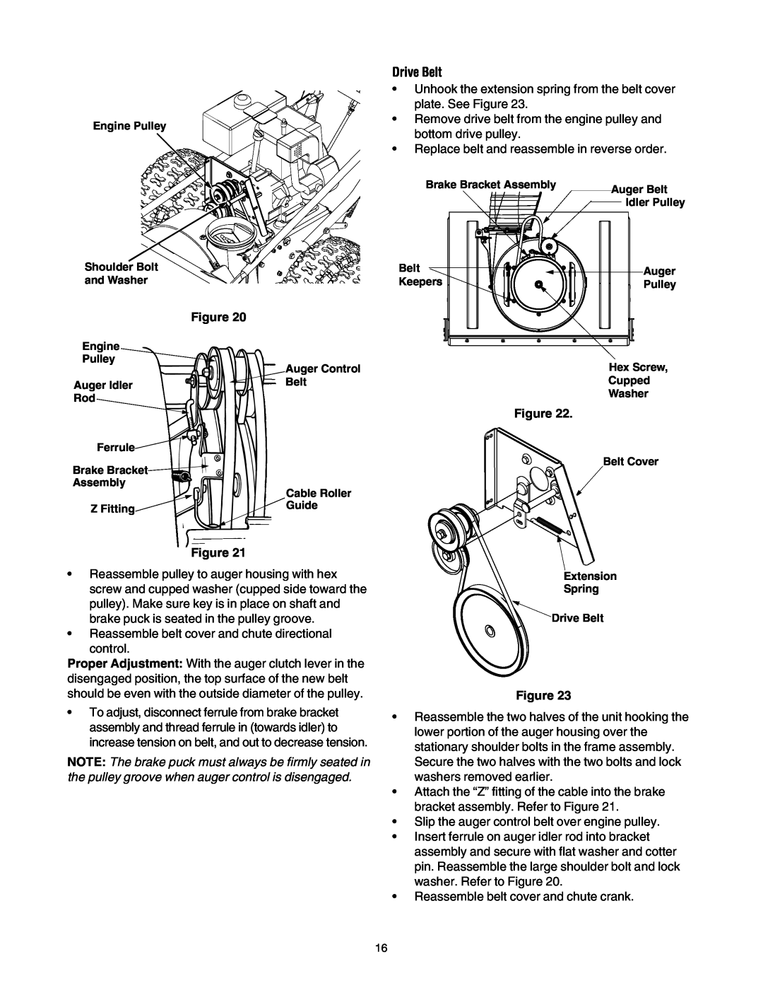
Engine Pulley
Shoulder Bolt
and Washer
Figure 20
Engine
Pulley
| Auger Control |
Auger Idler | Belt |
| |
Rod |
|
Ferrule |
|
Brake Bracket |
|
Assembly | Cable Roller |
| |
Z Fitting | Guide |
|
Figure 21
•Reassemble pulley to auger housing with hex screw and cupped washer (cupped side toward the pulley). Make sure key is in place on shaft and brake puck is seated in the pulley groove.
•Reassemble belt cover and chute directional control.
Proper Adjustment: With the auger clutch lever in the disengaged position, the top surface of the new belt should be even with the outside diameter of the pulley.
•To adjust, disconnect ferrule from brake bracket assembly and thread ferrule in (towards idler) to increase tension on belt, and out to decrease tension.
NOTE: The brake puck must always be firmly seated in the pulley groove when auger control is disengaged.
Drive Belt
•Unhook the extension spring from the belt cover plate. See Figure 23.
•Remove drive belt from the engine pulley and bottom drive pulley.
•Replace belt and reassemble in reverse order.
Brake Bracket Assembly |
| Auger Belt | ||||||||||||||
|
|
|
|
|
|
|
|
|
|
|
|
|
|
| ||
|
|
|
|
|
|
|
|
|
|
|
|
|
|
|
| Idler Pulley |
|
|
|
|
|
|
|
|
|
|
|
|
|
| |||
|
|
|
|
|
|
|
|
|
|
|
|
|
| |||
|
|
|
|
|
|
|
|
|
|
|
|
|
|
|
| |
|
|
|
|
|
|
|
|
|
|
|
|
|
|
|
|
|
Belt | Auger |
Keepers | Pulley |
Hex Screw,
Cupped
Washer
Figure 22.
Belt Cover
Extension
Spring
Drive Belt
Figure 23
•Reassemble the two halves of the unit hooking the lower portion of the auger housing over the stationary shoulder bolts in the frame assembly. Secure the two halves with the two bolts and lock washers removed earlier.
•Attach the “Z” fitting of the cable into the brake bracket assembly. Refer to Figure 21.
•Slip the auger control belt over engine pulley.
•Insert ferrule on auger idler rod into bracket assembly and secure with flat washer and cotter pin. Reassemble the large shoulder bolt and lock washer. Refer to Figure 20.
•Reassemble belt cover and chute crank.
16