Manuals
/
Yazoo/Kees
/
Lawn and Garden
/
Lawn Mower
Yazoo/Kees
ZPKW5426
manual
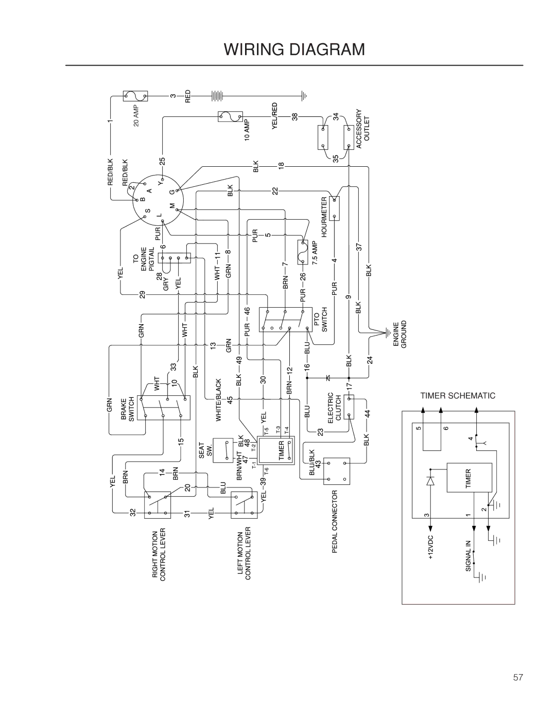
Wiring Diagram
Models:
ZPKW5426
1
57
72
72
Download
72 pages
20.21 Kb
54
55
56
57
58
59
60
61
Troubleshooting
Specification
Install
Wiring Diagram
Symbols and decals
Dimension
Maintenance
Weak Battery
Purging Procedures
Seat Adjustment Lever
Page 57
Image 57
WIRING DIAGRAM
TIMER SCHEMATIC
57
Page 56
Page 58
Page 57
Image 57
Page 56
Page 58
Contents
Operator Manual
Page
Contents
Page
Introduction
Manufacturing Number
Good Service
Symbols and decals
Manual Performing any
Safety
Safety Instructions
General Operation
Never take passengers
Slope Operation
Personal Safety Equipment
Children
Safe Handling of Gasoline
General Maintenance
Risk of sparking
Transport
Spark Arrestors
Rollover Protection System Rops
Control Locations
Controls
Motion Control Levers
Tracking
Hour Meter
Blade Switch
Ignition Switch
Parking Brake
Ignition switch RUN position
Fuses
Choke Control
Cutting Height Pedals
Fuel Shut Off Valve
Seat Adjustment Lever
Refueling
Operation
Training
Steering
Before Starting
Roll Bar and Safety Belt
Starting the Engine
Set the throttle
Turn to Start position
Push choke in after starting
Weak Battery
Jumper Cables
To remove cables, reverse order
Running
Operating on Hills
Ensure that no one is near mower when engaging blade switch
Stopping the Engine
Mowing Tips
Manual Transport
Maintenance
Maintenance
Battery
For cleaning
For replacing
Safety System
Fuel Filter
Tire Pressures
Parking brake adjustment
Neutral Adjustments
Deck Belt Installation
Deck Belt
Deck Belt Removal
Pump Belt
Belt Installation
Belts
Replacing Pump Belt
Cutting Blades
Leveling Deck
Adjusting the Mower Deck
Deck Lift Spring
Anti-scalp Rollers
Removal and Installation
Cleaning
Use protective glasses when cleaning and washing
Caster Wheels
Lubrication
Lubrication Schedule
General
Cables
Wheel and Deck Zerks
Front Wheel Mount
Front Wheel Bearings
Fluid Change
Hydraulic Drive
Purging Procedures
Problem Cause
Troubleshooting guide
Troubleshooting guide
Service
Storage
Winter Storage
Wiring Diagram
Technical Data
ZPKW5426 ZPKW6029 Engine
Transmission
ZPKW5426 ZPKW6029 Frame
Dimension
Hex Head Cap Screws
Torque Specifications
Standard Hardware
Metric Standard Hardware
CE requirements
USA requirements
Delivery Service
Service Journal
Action
Stamp, sign
Date, mtr reading Stamp, sign
After 10 hours
Daily Service
Hour Service
Service Journal
Service Journal
At least once each year
Action Date, mtr reading Stamp, sign
Service Journal
Page
115 263226R1 09/21/09
Top
Page
Image
Contents