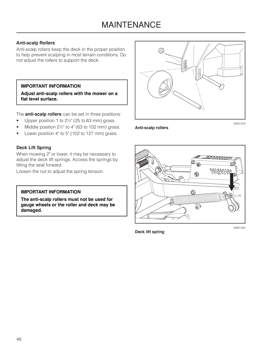
Operator Manual
ZPKW5426 / 966494701 ZPKW6029
2009 HTC. All rights reserved. Beatrice, NE. Printed in U.S.A
Contents
Page
INTRODUCTION
Congratulations
General
Driving and Transport on Public Roads
Good Service
Manufacturing Number
Please have these available when ordering spare parts
INTRODUCTION
symbols and decals
Xxxx xxxxxx xxxxx xxxx xxxxxxxxx xxxxxx xxxxxxxxx. xx xxxxxxxx xxxx
IMPORTANT INFORMATION
symbols and decals
remove safety
Manual
performing any
SAFETY
Safety Instructions
General Operation
SAFETY
Watch for traffic when operating near or crossing roadways
Personal Safety Equipment
Slope Operation
SAFETY
Children
SAFETY
Safe Handling of Gasoline
The engine and the exhaust system become very hot during operation
There is risk for burns if touched
SAFETY
General Maintenance
Use protective glasses for maintenance work
SAFETY
SAFETY
Use protective goggles
if proper medical treatment is not administered immediately
Transport
SAFETY
IMPORTANT INFORMATION
Rollover Protection System ROPS
Spark Arrestors
SAFETY
The engine and the exhaust system become very hot during operation
CONTROLS
Control Locations
Motion Control Levers
CONTROLS
1. Forward 2. Neutral 3. Neutral slot, Neutral lock 4. Reverse
Hour Meter
Tracking
CONTROLS
Blade Switch
Ignition Switch
Parking Brake
CONTROLS
Release the key to the RUN position when the engine has started
For using “accessory”, turn the key counter clockwise
Ignition switch - RUN position
Ignition switch - accessory
Fuses
Choke Control
Cutting Height Pedals
CONTROLS
Seat Adjustment Lever
Fuel Shut Off Valve
Lengthways adjustment
CONTROLS
Refueling
Risk for burns if touched
CONTROLS
IMPORTANT INFORMATION
OPERATION
Training
Steering
To move forward and backward
Roll Bar and Safety Belt
The seat belt must be used when the roll bar is in upright position
Before Starting
OPERATION
Starting the Engine
OPERATION
OPERATION
6. Move the throttle to the middle position
8. Open the fuel tank valve
Set the throttle
OPERATION
9. Press in and turn the ignition key to the start position
IMPORTANT INFORMATION
Turn to START position
11. Push the choke control in gradually when the engine has started
OPERATION
Weak Battery
Lead-acid batteries generate
The mower is equipped with a 12-volt negative
grounded system. The other vehicle must also
Running
OPERATION
Ensure that no one is near mower when engaging blade switch
Operating on Hills
OPERATION
IMPORTANT INFORMATION
Stopping the Engine
OPERATION
Mowing Tips
OPERATION
No adjustments or maintenance should be carried out unless
Manual Transport
IMPORTANT INFORMATION Tighten the valve moderately
Pump Release Valves
maintenance
Before performing any service or adjustment checklist
Place the Blade-switch in the disengaged position
Turn the ignition switch to “OFF” position and remove the key
Engage the parking brake
Battery
Always wear eye protection when around batteries Battery Removal
For cleaning
For replacing
Safety System
Fuel Filter
Tire Pressures
Only use O.E.M. specified tires
The machine must be standing still when applying the parking brake
Parking Brake Adjustments
maintenance
Parking Brake
Neutral Adjustments
maintenance
Deck Belt Installation
Deck Belt
Deck Belt Removal
maintenance
Belt Installation
Pump Belt
V-belts
Replacing Pump Belt
Blade Replacement
Cutting Blades
IMPORTANT INFORMATION Special blade bolt is heat treated
Replace with a Yazoo/Kees bolt if required
Adjusting the Mower Deck
Leveling Deck
maintenance
1. Adjustment bolt 2. Locknut
Adjust anti-scalp rollers with the mower on a flat level surface
Anti-scalp Rollers
Deck Lift Spring
maintenance
Cleaning
Removal and Installation
Use protective glasses when cleaning and washing
Caster Wheels
LUBRICATION
Lubrication Schedule
General
Wheel and Deck Zerks
Cables
Front Wheel Mount
Front Wheel Bearings
Hydraulic Drive
Fluid Change
LUBRICATION
Purging Procedures
LUBRICATION
troubleshooting guide
Problem
Cause
troubleshooting guide
Problem
Cause
Service
STORAGE
Winter Storage
a degreaser and warm water
WIRING DIAGRAM
TIMER SCHEMATIC
TECHNICAL DATA
ZPKW5426
ZPKW6029
Engine
Dimension
Frame
TECHNICAL DATA
ZPKW5426
Torque Specifications
Hex Head Cap Screws
U.S. Standard Hardware
Metric Standard Hardware
conformity certificates
USA requirements
CE requirements
SERVICE JOURNAL
Delivery Service
Action
stamp, sign
After 10 hours
Date, mtr reading stamp, sign
SERVICE JOURNAL
7. Check neutral position 8. Check safety system 9. Check seat belt
Daily Service
SERVICE JOURNAL
Action
stamp, sign
50-Hour Service
SERVICE JOURNAL
Action
Date, mtr reading stamp, sign
250-Hour Service
SERVICE JOURNAL
Action
stamp, sign
500-Hour Service
SERVICE JOURNAL
Action
stamp, sign
At least once each year
SERVICE JOURNAL
Action
stamp, sign
SERVICE JOURNAL
Action
Date, mtr reading stamp, sign
SERVICE JOURNAL
Action
Date, mtr reading stamp, sign
Page
P/N 115 263226R1
09/21/09