REFER TO ELECTRICAL
DATA TABLES TO SIZE THE
DISCONNECT SWITCH,
WIRING & OVERCURRENT
24 VOLT TRANSFORMER

035-18265-001-A-0202

Refer to Figure 5 for information concerning rear and bottom supply and return air duct openings.

Refer to Figure 5 for location of these access panels and mini- mum clearances.

ROOF CURB

On applications when a roof curb is used, the unit must be posi- tioned on the curb so the front of the unit is tight against the curb.

FILTERS

Single phase units are shipped without a filter and is the responsi- bility of the installer to secure a filter in the return air ductwork or install a Filter/Frame Kit (1FF0110 for the D1NA018 thru D1NA042 and 1FF0112 for the D1NA048 and D2NA060).

A filter rack and filters are standard on three phase units.

NOTE: Filters on the D1NA048 and D2NA060 units require the use of a 516 " nut driver for removal.

Filters must always be used and must be kept clean. When fil- ters become dirt laden, insufficient air will be delivered by the blower, decreasing your units efficiency and increasing operat- ing costs and wear-and-tear on the unit and controls.

Filters should be checked monthly especially since this unit is used for both heating and cooling.

THERMOSTAT

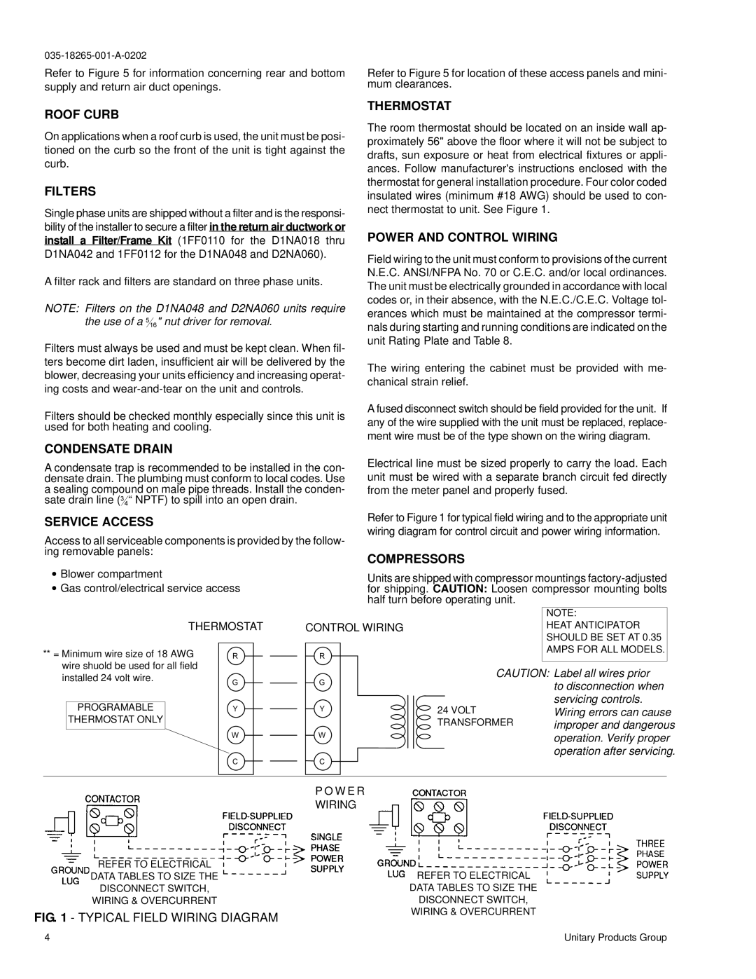
The room thermostat should be located on an inside wall ap- proximately 56" above the floor where it will not be subject to drafts, sun exposure or heat from electrical fixtures or appli- ances. Follow manufacturer's instructions enclosed with the thermostat for general installation procedure. Four color coded insulated wires (minimum #18 AWG) should be used to con- nect thermostat to unit. See Figure 1.

POWER AND CONTROL WIRING

Field wiring to the unit must conform to provisions of the current N.E.C. ANSI/NFPA No. 70 or C.E.C. and/or local ordinances. The unit must be electrically grounded in accordance with local codes or, in their absence, with the N.E.C./C.E.C. Voltage tol- erances which must be maintained at the compressor termi- nals during starting and running conditions are indicated on the unit Rating Plate and Table 8.

The wiring entering the cabinet must be provided with me- chanical strain relief.

A fused disconnect switch should be field provided for the unit. If any of the wire supplied with the unit must be replaced, replace- ment wire must be of the type shown on the wiring diagram.

CONDENSATE DRAIN

A condensate trap is recommended to be installed in the con- densate drain. The plumbing must conform to local codes. Use a sealing compound on male pipe threads. Install the conden- sate drain line (34“ NPTF) to spill into an open drain.

Electrical line must be sized properly to carry the load. Each unit must be wired with a separate branch circuit fed directly from the meter panel and properly fused.

SERVICE ACCESS

Access to all serviceable components is provided by the follow- ing removable panels:

Blower compartment

Gas control/electrical service access

Refer to Figure 1 for typical field wiring and to the appropriate unit wiring diagram for control circuit and power wiring information.

COMPRESSORS

Units are shipped with compressor mountings factory-adjusted for shipping. CAUTION: Loosen compressor mounting bolts half turn before operating unit.

THERMOSTAT

CONTROL WIRING

** = Minimum wire size of 18 AWG

R

R

wire shuold be used for all field


installed 24 volt wire.

G

G


PROGRAMABLE

Y

Y

THERMOSTAT ONLY


W

W

NOTE:

HEAT ANTICIPATOR

SHOULD BE SET AT 0.35

AMPS FOR ALL MODELS.

CAUTION: Label all wires prior to disconnection when servicing controls. Wiring errors can cause improper and dangerous operation. Verify proper operation after servicing.

CC

P O W E R

WIRING

REFER TO ELECTRICAL

DATA TABLES TO SIZE THE

DISCONNECT SWITCH,

WIRING & OVERCURRENT

FIG. 1 - TYPICAL FIELD WIRING DIAGRAM

4

Unitary Products Group

Page 4
Image 4
York D2NA060 Roof Curb, Filters, Thermostat, Power and Control Wiring, Condensate Drain, Service Access, Compressors

D1NA018, D2NA060 specifications

The York D1NA018 and D2NA060 are advanced rooftop air conditioning units that combine efficiency, reliability, and innovative technologies to provide optimal climate control for commercial buildings. These units are designed to deliver robust performance while ensuring ease of installation and maintenance.

The D1NA018 is a compact model with a nominal cooling capacity of 1.5 tons, making it an ideal choice for smaller commercial spaces or applications where space is limited. In contrast, the D2NA060 offers a higher cooling capacity of 5 tons, catering to larger areas or environments that require more substantial cooling solutions. Both units are built with high-quality materials that enhance their durability and extend their operational life.

One of the key features of both models is their energy efficiency. They utilize advanced scroll compressor technology that ensures a quieter operation while optimizing energy consumption. The units are designed to achieve high Seasonal Energy Efficiency Ratios (SEER), which makes them compliant with modern energy regulations. This not only reduces operational costs but also minimizes the environmental impact.

Additionally, the York D1NA018 and D2NA060 come equipped with enhanced airflow technologies. They feature multi-speed blowers that can adapt to varying load conditions, ensuring consistent temperature control throughout the indoor space. The airflow systems are designed to provide even distribution, enhancing comfort for occupants.

These units are also equipped with user-friendly control options. The integrated digital controls allow for precise temperature management and programming, further increasing efficiency. Building managers can easily monitor and control the units, leading to improved operational convenience.

Another standout characteristic is their ease of installation. The compact design and lightweight construction of the D1NA018 simplify rooftop installations. The D2NA060, while larger, maintains a straightforward installation process, ensuring minimal disruption to building operations.

In terms of maintenance, the York D1NA018 and D2NA060 incorporate features that facilitate routine service and upkeep. Access panels are strategically placed, allowing technicians to reach components quickly and perform necessary maintenance checks with ease.

Overall, the York D1NA018 and D2NA060 represent a blend of efficiency, innovation, and practicality, making them suitable choices for a wide range of commercial applications. Their advanced technologies provide reliable climate control while reducing energy consumption, making them a preferred option for businesses seeking sustainable solutions.