035-18265-001-A-0202


3. Use wrought iron or steel pipe for all gas lines. Pipe dope


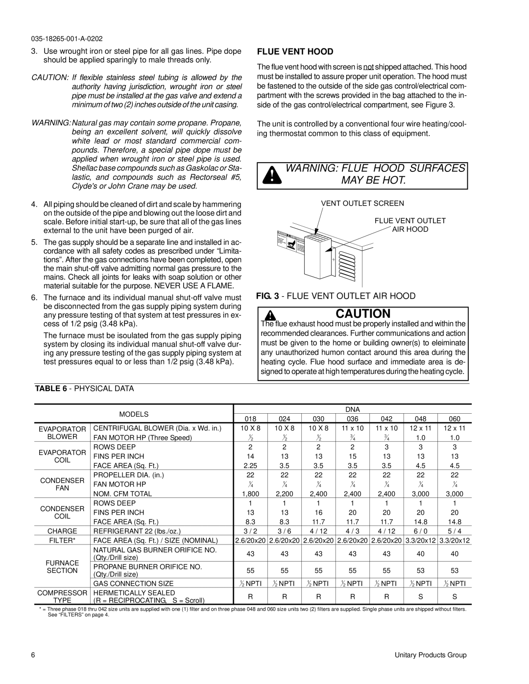
FLUE VENT HOOD


should be applied sparingly to male threads only.


The flue vent hood with screen is not shipped attached. This hood


CAUTION: If flexible stainless steel tubing is allowed by the


must be installed to assure proper unit operation. The hood must


authority having jurisdiction, wrought iron or steel


be fastened to the outside of the side gas control/electrical com-


pipe must be installed at the gas valve and extend a


partment with the screws provided in the bag attached to the in-


minimum of two (2) inches outside of the unit casing.


side of the gas control/electrical compartment, see Figure 3.

WARNING: Natural gas may contain some propane. Propane,


The unit is controlled by a conventional four wire heating/cool-


being an excellent solvent, will quickly dissolve


ing thermostat common to this class of equipment.


white lead or most standard commercial com-


pounds. Therefore, a special pipe dope must be


applied when wrought iron or steel pipe is used.


Shellac base compounds such as Gaskolac or Sta-


WARNING: FLUE HOOD SURFACES


lastic, and compounds such as Rectorseal #5,


MAY BE HOT.


Clyde's or John Crane may be used.


4. All piping should be cleaned of dirt and scale by hammering


V E N T

O U T L E T S C R E E N


on the outside of the pipe and blowing out the loose dirt and


scale. Before initial start-up, be sure that all of the gas lines


F L U E

V E N T O U T L


external to the unit have been purged of air.


A I R

H O O D

5. The gas supply should be a separate line and installed in ac-


cordance with all safety codes as prescribed under “Limita-


tions”. After the gas connections have been completed, open


the main shut-off valve admitting normal gas pressure to the


mains. Check all joints for leaks with soap solution or other


material suitable for the purpose. NEVER USE A FLAME.


6. The furnace and its individual manual shut-off valve must

FIG. 3 - FLUE VENT OUTLET AIR HOOD


be disconnected from the gas supply piping system during


CAUTION


any pressure testing of that system at test pressures in ex-


cess of 1/2 psig (3.48 kPa).


The flue exhaust hood must be properly installed and within the


The furnace must be isoulated from the gas supply piping


recommended clearances. Further communications and action


must be given to the home or building owner(s) to eleiminate


system by closing its individual manual shut-off valve dur-


ing any pressure testing of the gas supply piping system at


any unauthorized humon contact around this area during the


test pressures equal to or less than 1/2 psig (3.48 kPa).


heating cycle. Flue hood surface and immediate area is de-


signed to operate at high temperatures during the heating cycle.


TABLE 6 - PHYSICAL DATA


MODELS


DNA


018


024

030

036

042


048


060


EVAPORATOR

CENTRIFUGAL BLOWER (Dia. x Wd. in.)


10 X 8

10 X 8

10 X 8

11 x 10

11 x 10


12 x 11


12 x 11


BLOWER

FAN MOTOR HP (Three Speed)


12


12

12

34

34


1.0


1.0


EVAPORATOR

ROWS DEEP


2


2

2

2

3


3


3


FINS PER INCH


14


13

13

15

13


13


13


COIL


FACE AREA (Sq. Ft.)


2.25


3.5

3.5

3.5

3.5


4.5


4.5


PROPELLER DIA. (in.)


22


22

22

22

22


22


22


CONDENSER

FAN MOTOR HP


14


14

14

14

14


14


14


FAN

NOM. CFM TOTAL


1,800

2,200

2,400

2,400

2,400


3,000


3,000


CONDENSER

ROWS DEEP


1


1

1

1

1


1


1


FINS PER INCH


13


13

16

20

20


20


20


COIL


FACE AREA (Sq. Ft.)


8.3


8.3

11.7

11.7

11.7


14.8


14.8


CHARGE

REFRIGERANT 22 (lbs./oz.)


3 / 2


3 / 6

4 / 12

4 / 3

4 / 12


6 / 0


5 / 4


FILTER*

FACE AREA (Sq. Ft.) / SIZE (NOMINAL)


2.6/20x20

2.6/20x20

2.6/20x20

2.6/20x20

2.6/20x20

3.3/20x12

3.3/20x12


NATURAL GAS BURNER ORIFICE NO.


43


43

43

43

43


40


40


(Qty./Drill size)


FURNACE


PROPANE BURNER ORIFICE NO.


55


55

55

55

55


53


53


SECTION


(Qty./Drill size)


1


1

1

1

1


1


1


GAS CONNECTION SIZE


2NPTI

2NPTI

2NPTI

2NPTI

2NPTI


2NPTI


2NPTI


COMPRESSOR

HERMETICALLY SEALED


R

R

R

R

R


S


S


TYPE

(R = RECIPROCATING, S = Scroll)


*= Three phase 018 thru 042 size units are supplied with one (1) filter and on three phase 048 and 060 size units two (2) filters are supplied. Single phase units are shipped without filters. See “FILTERS” on page 4.

6

Unitary Products Group

Page 6
Image 6
York D2NA060, D1NA018 installation instructions Flue Vent Hood, Physical Data

D1NA018, D2NA060 specifications

The York D1NA018 and D2NA060 are advanced rooftop air conditioning units that combine efficiency, reliability, and innovative technologies to provide optimal climate control for commercial buildings. These units are designed to deliver robust performance while ensuring ease of installation and maintenance.

The D1NA018 is a compact model with a nominal cooling capacity of 1.5 tons, making it an ideal choice for smaller commercial spaces or applications where space is limited. In contrast, the D2NA060 offers a higher cooling capacity of 5 tons, catering to larger areas or environments that require more substantial cooling solutions. Both units are built with high-quality materials that enhance their durability and extend their operational life.

One of the key features of both models is their energy efficiency. They utilize advanced scroll compressor technology that ensures a quieter operation while optimizing energy consumption. The units are designed to achieve high Seasonal Energy Efficiency Ratios (SEER), which makes them compliant with modern energy regulations. This not only reduces operational costs but also minimizes the environmental impact.

Additionally, the York D1NA018 and D2NA060 come equipped with enhanced airflow technologies. They feature multi-speed blowers that can adapt to varying load conditions, ensuring consistent temperature control throughout the indoor space. The airflow systems are designed to provide even distribution, enhancing comfort for occupants.

These units are also equipped with user-friendly control options. The integrated digital controls allow for precise temperature management and programming, further increasing efficiency. Building managers can easily monitor and control the units, leading to improved operational convenience.

Another standout characteristic is their ease of installation. The compact design and lightweight construction of the D1NA018 simplify rooftop installations. The D2NA060, while larger, maintains a straightforward installation process, ensuring minimal disruption to building operations.

In terms of maintenance, the York D1NA018 and D2NA060 incorporate features that facilitate routine service and upkeep. Access panels are strategically placed, allowing technicians to reach components quickly and perform necessary maintenance checks with ease.

Overall, the York D1NA018 and D2NA060 represent a blend of efficiency, innovation, and practicality, making them suitable choices for a wide range of commercial applications. Their advanced technologies provide reliable climate control while reducing energy consumption, making them a preferred option for businesses seeking sustainable solutions.