|
| |||
| TABLE OF CONTENTS |
| ||
General | 1 | MAINTENANCE & TROUBLESHOOTING | ||
Inspection | 1 | Normal Maintenance | 17 | |
Reference | 1 | |||
Cleaning Flue Passages and Heating Elements | 17 | |||
Approvals | 1 | |||
Troubleshooting | 18 & 19 | |||
Nomenclature | 2 | |||
|
| |||
INSTALLATION |
|
Limitations | 3 |
Location | 3 |
Rigging and Handling | 3 |
Clearances | 3 |
Ductwork | 3 |
Filters | 4 |
Condensate Drain | 4 |
Service Access | 4 |
Thermostat | 4 |
Power and Control Wiring | 4 |
Blower Speed Selection | 4 |
Compressors | 4 |
Combustion Discharge | 4 |
Disconnect Switch Bracket For Optional | 5 |
Gas Piping | 5 |
Gas Connection | 6 |
L.P. Units, Tanks and Piping | 6 |
Low NOx Application | 6 |
Vent and Combustion Air Hoods | 7 |
Optional Economizer Rain Hood | 7 |
OPERATION |
|
Cooling System | 13 |
Preliminary Operation Cooling | 13 |
Cooling Sequence of Operation | 13 |
Safety Controls (Cooling) | 13 |
Heating Sequence of Operation | 13 |
Safety Controls (Heating) | 14 |
Heat Anticipator Setpoints | 14 |
14 | |
| |
Operating Instructions | 14 |
14 | |
Manifold Gas Pressure Adjustment | 14 |
Pilot Checkout | 15 |
Burner Instructions | 15 |
Burner Air Shutter Adjustment | 15 |
Supply Air Blower and Temperature Rise Adj | 15 |
Supply Air Blower and Temperature Rise Adj | 15&16 |
Checking Gas Input | 16 |
Secure Owner's Approval | 16 |
| TABLES |
|
No. | Description | Page |
1 | Unit Application Data | 3 |
2 | Gas Heat Application Data | 4 |
3 | Pipe Sizing | 5 |
4 | Physical Data | 8 |
5 | Supply Air Perf. | 8 |
6 | Supply Air Perf.3 & 4Ton | 9 |
7 | Supply Air Perf.5 Ton | 10 |
8 | Static Resistances | 11 |
9 | Motor & Drive Data | 11 |
10 | Electrical Data | 11 |
11 | Electrical Data | 11 |
12 | Limit Control Setting | 14 |
13 | 15 | |
14 | Gas Rate - Cubic Feet Per Hour | 16 |
| FIGURES |
|
No. | Description | Page |
1 | Center of Gravity | 3 |
2 | Recommended Drain Piping | 4 |
3 | Typical Field Wiring | 5 |
4 | External Supply Connection | 6 |
5 | Bottom Supply Connection | 6 |
6 | Vent and Combustion Air Hoods | 7 |
7 | Economizer Rain Hood Assembly | 7 |
8 | Enthalpy Setpoint Adjustment | 8 |
9 | Dimensions and Clearances | 12 |
10 | Gas Valve Piping | 13 |
11 | Typical Gas Valve | 14 |
12 | Proper Flame Adjustment | 15 |
13 | Typical Flame Appearance | 15 |
14 | Belt Adjustment | 15 |
15 | Press. Drop versus Supply Air CFM | 16 |
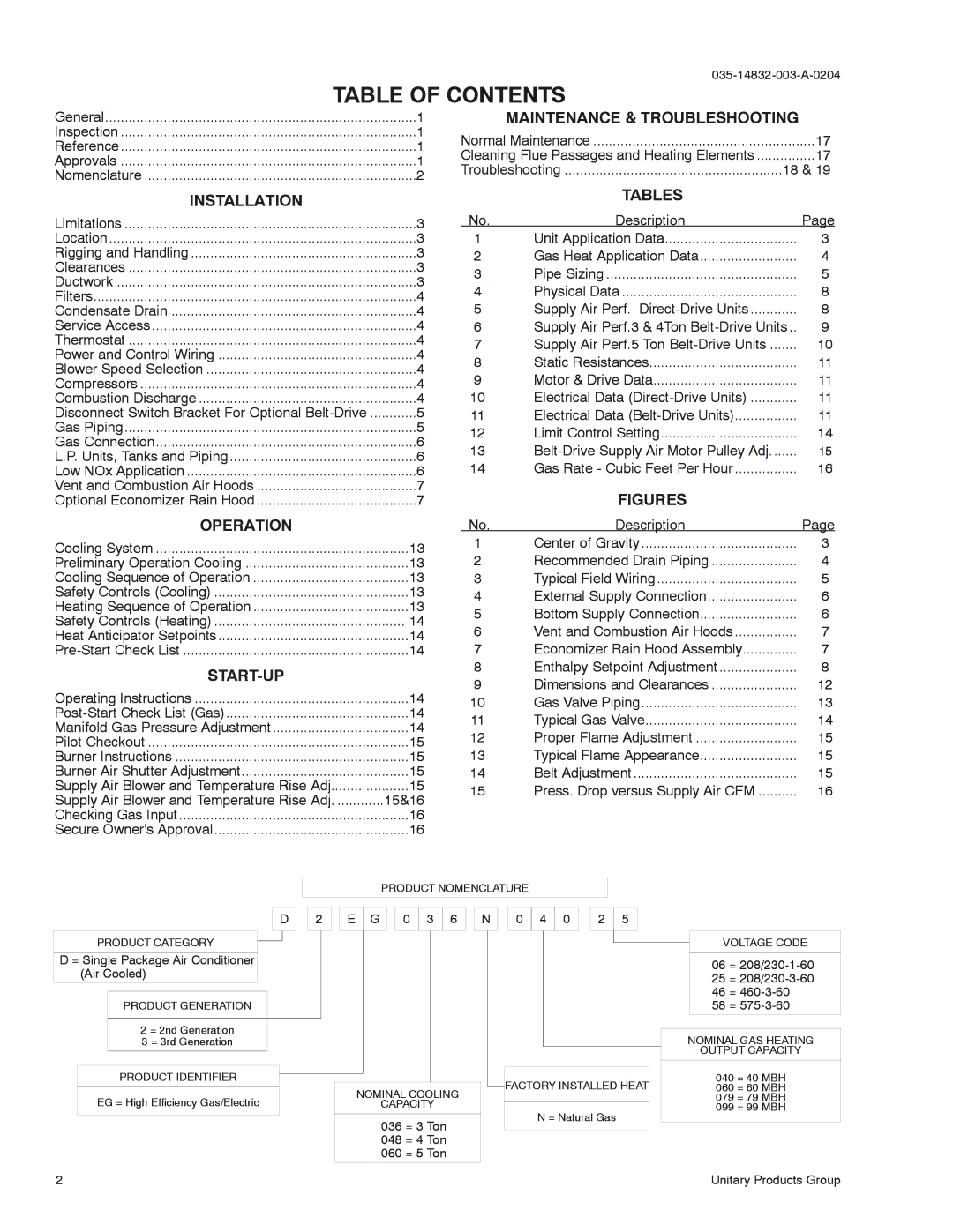
D
PRODUCT CATEGORY
D = Single Package Air Conditioner (Air Cooled)
PRODUCT GENERATION
2 = 2nd Generation
3 = 3rd Generation
PRODUCT IDENTIFIER
EG = High Efficiency Gas/Electric
2
PRODUCT NOMENCLATURE
2 ![]()
![]() E
E ![]() G
G ![]()
![]() 0
0 ![]()
![]() 3
3 ![]() 6
6 ![]()
![]() N
N ![]()
![]() 0
0 ![]() 4
4 ![]() 0
0 ![]()
![]() 2
2 ![]()
![]() 5
5
|
|
| FACTORY INSTALLED HEAT |
NOMINAL COOLING |
|
|
|
CAPACITY |
|
|
|
|
| N = Natural Gas | |
|
|
| |
036 = 3 Ton |
|
| |
|
|
| |
048 = 4 Ton |
|
|
|
060 = 5 Ton |
|
|
|
VOLTAGE CODE
06 =
25 =
46 =
58 =
NOMINAL GAS HEATING
OUTPUT CAPACITY
040 = 40 MBH
060 = 60 MBH
079 = 79 MBH
099 = 99 MBH
Unitary Products Group