COOLING / HEATING (24 VOLT THERMOSTAT)
COOLING/HEATING(24VOLTTHERMOSTAT)
THERMOSTAT1
TERMINALS
| UNITTERMINAL |
|
RH | STRIPTB1 |
|
ADD |
| |
|
| |
JUMPER RC | R |
|
Y | Y1 | 24VOLT |
|
|
TRANSFORMER
Y2
WW1
W2
GG
B
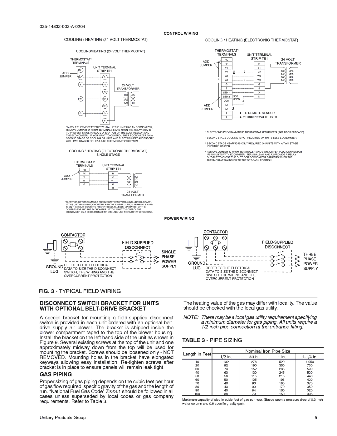
124VOLTTHERMOSTAT2TH07701024.IFTHEUNITHASANECONOMIZER, REMOVEJUMPERJ1FROMTERMINALS8AND10ONTHERELAYBOARD TOPREVENTSIMULTANEOUSOPERATIONOFTHECOMPRESSORAND THEECONOMIZER.IFYOUWANTTOCONTROLTHERECONOMIZERONA SECONDSTAGEOFCOOLINGORHAVEANDELECTRICHEATACCESSORY WITHTWOSTAGESOFHEAT,USETHERMOSTAT2TH0471024
COOLING/HEATING(ELECTRONICTHERMOSTAT)
SINGLESTAGE
THERMOSTAT1
TERMINALS UNITTERMINAL
RH STRIPTB1
| RC |
| R |
ADD |
|
|
|
Y |
| Y1 | |
JUMPER |
|
|
|
W |
| W1 | |
|
| ||
|
|
|
|
| G |
| G |
|
|
|
|
|
|
| B |
|
|
|
|
24VOLT
TRANSFORMER
1ELECTRONICPROGRAMMABLETHERMOSTAT2ET07701024(INCLUDESSUBBASE).
IFTHISUNITHASANDECONOMIZER,REMOVEJUMPERJ1FROMTERMINALS8AND 10ONTHERELAYBOARDTOPREVENTSIMULTANEOUSOPERATIONOFTHE COMPRESSORANDTHEECONOMIZER.IFYOUWANTTOCONTROLTHE ECONOMIZERONASECONDSTAGEOFCOOLING,USETHERMOSTAT2ET04700224.
REFER TO THE ELECTRICAL
DATA TO SIZE THE DISCONNECT
SWITCH, THE WIRING AND THE
OVERCURRENT PROTECTION
CONTROL WIRING
COOLING / HEATING (ELECTRONIC THERMOSTAT)
THERMOSTAT1 |
|
|
| ||
TERMINALS |
| UNITTERMINAL |
| ||
| RC |
|
| STRIPTB1 | 24VOLT |
ADD |
|
|
| ||
RH |
|
| R | TRANSFORMER | |
JUMPER |
|
| |||
|
|
|
|
| |
| Y1 |
|
| Y1 |
|
| Y2 | 2 | 2 | Y2 |
|
| W1 |
|
| W1 |
|
4 | W2 |
| 3 | W2 |
|
| G |
|
| G |
|
| B |
|
| B |
|
| LED1 |
|
| X |
|
| LED2 | NOT |
| N |
|
| COM | USED 4 |
|
| |
ADD | A1 | 3 |
|
|
|
|
|
|
| ||
JUMPER | A2 |
|
|
| |
T TOREMOTESENSOR
T 2TH040702224IFUSED
1ELECTRONICPROGRAMMABLETHERMOSTAT2ET04700224(INCLUDESSUBBASE)
2SECONDSTAGECOOLINGISNOTREQUIREDONUNITSLESSECONOMIZER.
3SECONDSTAGEHEATINGISONLYREQUIREDONUNITSWITHATWOSTAGE ELECTRICHEATER.
4REMOVEJUMBERJ2FROMTERMINALS4AND9ONJUMPERPLUGCONNECTOR P6ONUNITSWITHECONMIZER.TERMINALSA1ANDA2PROVIDEARELAY
POWER WIRING
REFER TO THE ELECTRICAL
DATA TO SIZE THE DISCONNECT
SWITCH, THE WIRING AND THE
OVERCURRENT PROTECTION
FIG. 3 - TYPICAL FIELD WIRING
DISCONNECT SWITCH BRACKET FOR UNITS | The heating value of the gas may differ with locality. The value | |||||||
WITH OPTIONAL | should be checked with the local gas utility. |
| ||||||
A special bracket for mounting a | NOTE: There may be a local gas utility requirement specifying | |||||||
switch is provided in each unit ordered with an optional belt- |
| a minimum diameter for gas piping. All units require a | ||||||
drive supply air blower. The bracket is shipped inside the |
| 1/2 inch pipe connection at the entrance fitting. | ||||||
blower compartment taped to the top of the blower housing. |
|
|
|
|
|
|
| |
Install the bracket on the left hand side of the unit as shown in | TABLE 3 - PIPE SIZING |
|
|
| ||||
Figure 9. Several existing screws at the top of the unit and one |
|
|
| |||||
|
|
|
|
|
|
| ||
approximately midway down from the top will be used for |
|
|
|
|
|
|
| |
mounting the bracket. Screws should be loosened only - NOT | Length in Feet |
|
| Nominal Iron Pipe Size |
| |||
REMOVED. Mounting holes in the bracket have elongated | 1/2 in. |
| 3/4 in. | 1 in. | ||||
|
|
| ||||||
keyways allowing easy installation. | 10 |
| 132 |
| 278 | 520 | 1,050 | |
bracket is in place to ensure panels will remain leak tight. | 20 |
| 92 |
| 190 | 350 | 730 | |
30 |
| 73 |
| 152 | 285 | 590 | ||
GAS PIPING | 40 |
| 63 |
| 130 | 245 | 500 | |
50 |
| 56 |
| 115 | 215 | 440 | ||
Proper sizing of gas piping depends on the cubic feet per hour | 60 |
| 50 |
| 105 | 195 | 400 | |
70 |
| 46 |
| 96 | 180 | 370 | ||
of gas flow required, specific gravity of the gas and the length of | 80 |
| 43 |
| 90 | 170 | 350 | |
run. “National Fuel Gas Code” Z223.1 should be followed in all | 90 |
| 40 |
| 84 | 160 | 320 | |
100 |
| 38 |
| 79 | 150 | 305 | ||
cases unless superseded by local codes or gas company |
|
| ||||||
Maximum capacity of pipe in cubic feet of gas per hour. (Based upon a pressure drop of 0.3 inch | ||||||||
requirements. Refer to Table 3. | ||||||||
water column and 0.6 specific gravity gas). |
|
|
| |||||
|
|
|
| |||||
Unitary Products Group | 5 |