GROUND"Heat-TERMINALSContactorSupplyrminalatControlSCRWORAirBlockElectric10MBlowerON:BoxElectricMotor


3-protection*wiring,ReferPHASEUSEtoCOPPERdisconnectLINEelectrical.VOLTAGECONDUCTORSdataswitchtoPOWERsizeandtheovercurrentONLYSUPPLYpowerCOTERMINALSNTACTORSMPRESON1M035GROUND-&3M16192-001-A-1001

Pumponly"Units


LUG

GROUNDLUG


Unitswith


HeatAccessory


TB1


TB2


R


R


R


C


OC


CX


W1YO2


YG2


YO2


GX


1 W1X


1


W1


R


HC


TERMINALS ON HEAT PUMP THERMOSTAT

Compressors

INDOOR UNIT

Control wiring (24-volt) OUTDOOR UNIT


refer to electrical data


to determine the proper


OutdoorwireFansizeMotors.

MinimumMaximumMnimumi

MaximumMinimum

WIRE IN ACCORDANCE WITH LOCAL AND NATIONAL ELECTRICAL CODES

1Only required when an electric heat accessory is used.

*All outdoor units and all heat pump only indoor units require dual element, time delay fuses. Circuit breakers can be used in lieu of fuses for indoor units with an electric heat accessory.

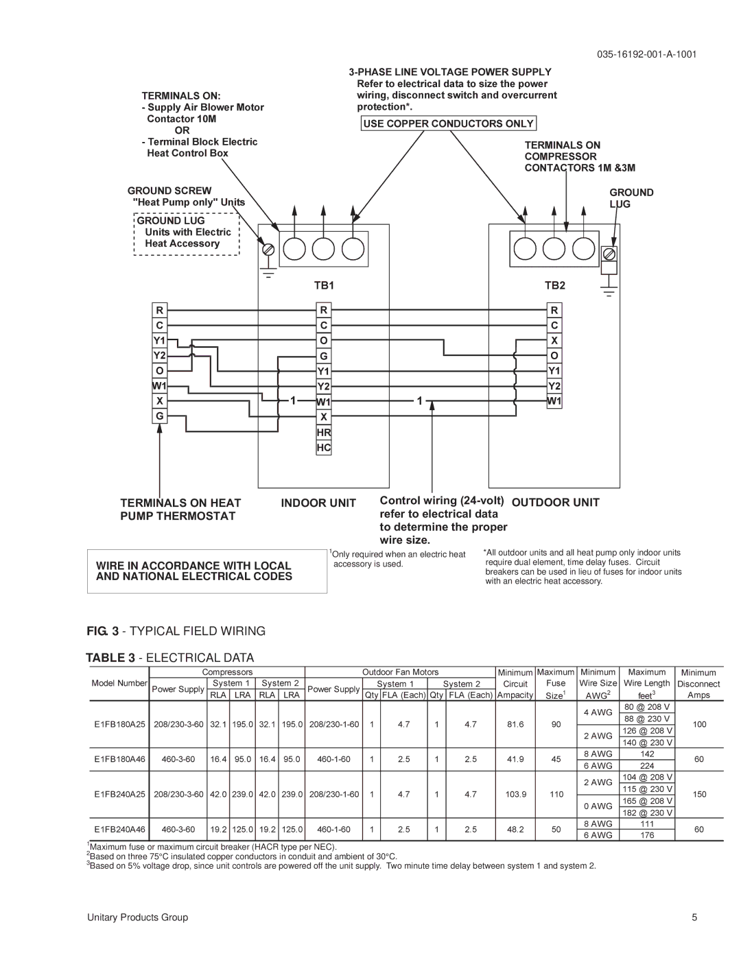
FIG. 3 - TYPICAL FIELD WIRING


AWG


TABLEModelE1FB240A18Number3254646025- ELECTRICALPower208/230208/230--Supply--6033--6060423216RLASystem...014DATA239195LRA...01System00324216RLA...014239195LRA...0200208/230208/230Power460-1Supply---6011--6060

Qty111SystemFLA442...(Each)7751

Qty111SystemFLA442...(Each)7752

Ampacity1038141Circuit...699

11090Size45Fuse501

W2468AWGreSize2

Wire8150426408@2feet22414Length230300808V

DisconnectAmps60150100


0

6

@ V


8

182


46460--6019.2125.19.2125. 460-1-60

1

2.5

1

2.5

48.2


11

60


6


176

1Maximum fuse or maximum circuit breaker (HACR type per NEC).

2Based on three 75°C insulated copper conductors in conduit and ambient of 30°C.

3Based on 5% voltage drop, since unit controls are powered off the unit supply. Two minute time delay between system 1 and system 2.

Unitary Products Group

5

Page 5
Image 5
York E1FB240, E1FB180 installation manual Typical Field Wiring, Wire in Accordance with Local and National Electrical Codes

E1FB240, E1FB180 specifications

The York E1FB180 and E1FB240 are part of York's advanced series of commercial heating and cooling systems, specifically designed to meet the dynamic needs of modern edifices. These models stand out due to their balance of efficiency, reliability, and innovative technology, making them ideal solutions for a myriad of industrial and commercial applications.

One of the main features of the York E1FB series is its impressive energy efficiency. Both the E1FB180 and E1FB240 incorporate high-efficiency compressors that significantly reduce electricity consumption while providing optimal performance. This energy efficiency is crucial not only for reducing operational costs but also for ensuring compliance with increasingly stringent environmental regulations.

In terms of technology, the E1FB series utilizes advanced inverter-driven technology. This feature allows the system to adjust its cooling and heating output based on real-time demand, enabling it to operate at varying speeds. Consequently, this results in quieter operation and a reduction in wear and tear on the components, prolonging the lifespan of the equipment.

Moreover, both models possess robust construction to withstand the rigors of commercial environments. They are built using high-quality materials that ensure durability and reliability even in challenging conditions. This is complemented by an array of corrosion-resistant features, making them suitable for installation in diverse geographical locations, including coastal areas where salt and moisture are prevalent.

The York E1FB180 and E1FB240 also come equipped with sophisticated control systems. These smart controls allow for easy integration into building management systems, enabling real-time monitoring and management. This integration facilitates better energy management practices, yielding further operational savings and improved efficiency.

Additionally, the E1FB series incorporates environmentally friendly refrigerants that align with global initiatives for reducing greenhouse gas emissions. This commitment to sustainability is a cornerstone of York’s design philosophy and is increasingly important for businesses seeking to enhance their green credentials.

In summary, the York E1FB180 and E1FB240 are exemplary models that reflect the brand's commitment to efficiency, durability, and advanced technology. Their innovative features make them a preferred choice for businesses looking to invest in reliable HVAC solutions that not only meet but exceed contemporary performance and environmental standards.