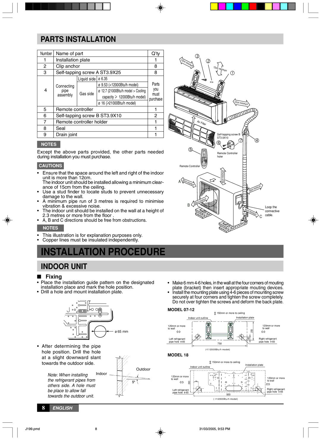
PARTS INSTALLATION

Number

Name of part


Q’ty

1

Installation plate


1

2

Clip anchor


8

3

Self-tapping screw A ST3.9X25

8


Liquid side

ø 6.35


Parts


Connecting


ø 9.53 (<12000Btu/h model)


4

pipe

Gas side

ø 12.7 (21000Btu/h model > Cooling


you


assembly

capacity f 12000Btu/h model)


must


purchase


ø 16 (f21000Btu/h model)


5

Remote controller


1

6

Self-tapping screw B ST3.9X10

2

7

Remote controller holder

1

8

Seal


1

9

Drain joint


1

NOTES

Except the above parts provided, the other parts needed during installation you must purchase.

CAUTIONS

Ensure that the space around the left and right of the indoor unit is more than 12cm.

The indoor unit should be installed allowing a minimum clear- ance of 15cm from the ceiling.

Use a stud finder to locate studs to prevent unnecessary damage to the wall.

A minimum pipe run of 3 metres is required to minimise vibration & excessive noise.

The indoor unit should be installed on the wall at a height of 2.3 metres or more from the floor .

A, B and C directions should be free from obstructions.

NOTES

This illustration is for explanation purposes only.

Copper lines must be insulated independently.

INSTALLATION PROCEDURE

INDOOR UNIT

Fixing

1


3


2c

m

min

2


imum

15cm

minim


um


1

12cm minimum


Air

F


ilter


Self-tapping screw B


ST3.9X10

7

4


6


5


Remote Controller


holer


Remote Controller


A


mi


minimum


30cm

nimum


60cm


um


im


min


30cm


nimum


mi


B

200cm


Loop the


60c


connective


m mi


nimu


m

C

cable.


Place the installation guide pattern on the designated installation place and mark the hole position.

Drill a hole and mount installation plate.

Make 6 mm 4-6 holes, in the wall at the four corners of mouting plate (bracket) then insert appropriate mouting devices.

Install the mounting plate using 4-6 pieces of mounting screw securely at four corners and tighten the screw completely. Do not over tighten the screws and deform the back plate.

MODEL 07-12

After determining the pipe hole position. Drill the hole at a slight downward slant towards the outdoor side.

Note: When installing

Indoor

the refrigerant pipes from


others side. A hole must


be place to allow fall


towards the outdoor unit.


ø 65 mm


.


.

.


.

.


.


.

.

.

.

.


.


.

.

.


.


.

.

.


.


.

.

.


.


.

.


.


.


.

.

.

.


.


.

.


.


.

.


.


.

.


.


.


.


.


.


Outdoor

.


.


.


.

.

.


.


.

.


.


.


.


.


.

.

.

.

.


.

.

.


.

.

.


.


.

.

.


.


.

.

.


.


.

.

.


.


.

.

.


.


.


.

.


.


.


.


.


.


.


.


.


.


.


.


.


.


.


.


.


.


.


.


.


.


.


.


.


.


.


.


.


.


.


.


150mm or more to ceiling


Indoor unit outline


Installation plate


120mm or more


120mm or more


to wall


250


to wall


45


Right refrigerant

Left refrigerant


pipe hole 65

750


pipe hole 65


(


12000Btu/h model)


MODEL 18


150mm or more to ceiling


Installation plate

Indoor unit outline


120mm or more


120mm or more


to wall


293


to wall

Left refrigerant


Right refrigerant

pipe hole 65


920


pipe hole 65


( 12000Btu/h model)


8ENGLISH

J199.pmd

8

31/03/2005, 9:53 PM

Page 8
Image 8
York MLCA-MLHA-07-24 owner manual Parts Installation, Indoor Unit, Fixing

MLCA-MLHA-07-24 specifications

York MLCA-MLHA-07-24 is a high-efficiency, cutting-edge variable refrigerant flow (VRF) system designed for both commercial and residential applications. This air conditioning solution embodies the latest advancements in HVAC technology, presenting significant energy-saving capabilities, versatile installation options, and enhanced user comfort.

One of the standout features of the York MLCA-MLHA-07-24 is its advanced inverter compressor technology. This technology allows the system to adjust its cooling or heating output based on the specific demands of the space, ensuring optimal energy use and maintaining desired indoor temperatures. By varying the compressor speed, the unit minimizes wear and tear on components, leading to a longer operational lifespan and reduced maintenance needs.

Another key characteristic of the MLCA-MLHA-07-24 is its multi-zone capability, which allows for efficient climate control in multiple rooms or areas. This flexibility permits individual temperature settings for different spaces, enhancing comfort for occupants while optimizing energy consumption. The system can support several indoor units connected to a single outdoor unit, making it ideal for various building layouts and sizes.

In terms of efficiency, the York MLCA-MLHA-07-24 boasts an impressive SEER (Seasonal Energy Efficiency Ratio) rating, which is indicative of its ability to cool spaces with minimal energy use. This promotes not only lower utility bills for end users but also contributes to a reduced carbon footprint, making it an environmentally friendly option in HVAC systems.

The system is also designed with quiet operation in mind. It features sound-dampening technologies that significantly lower noise levels, making it suitable for use in noise-sensitive environments. This is particularly beneficial in commercial settings such as offices, restaurants, and healthcare facilities where a peaceful atmosphere is essential.

Furthermore, the MLCA-MLHA-07-24 incorporates advanced controls with smart technology compatibility. Users can easily manage their indoor climate through mobile apps or smart home systems, providing convenience and the ability to monitor energy usage in real-time. This capability is rapidly becoming a necessity as energy management and sustainability become more significant priorities for consumers and businesses alike.

In conclusion, the York MLCA-MLHA-07-24 represents a synthesis of innovation, efficiency, and user-friendly operation. Its key technologies and characteristics make it a prime choice for those seeking to enhance their indoor environments through sophisticated HVAC solutions that prioritize comfort, sustainability, and convenience.