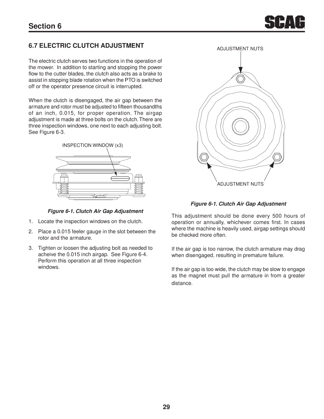
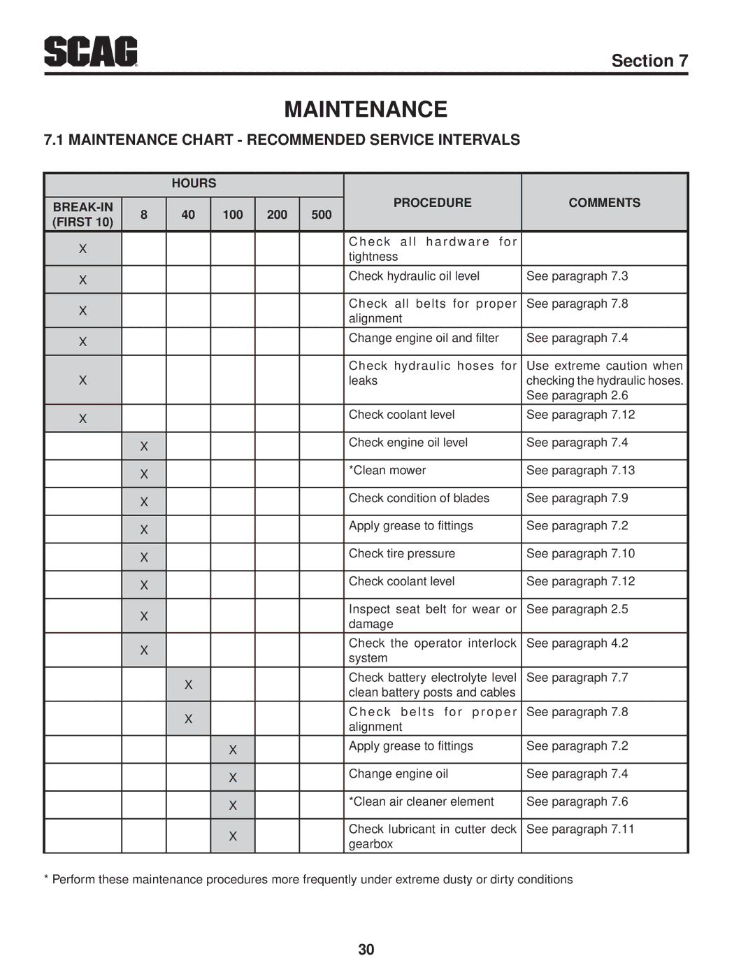
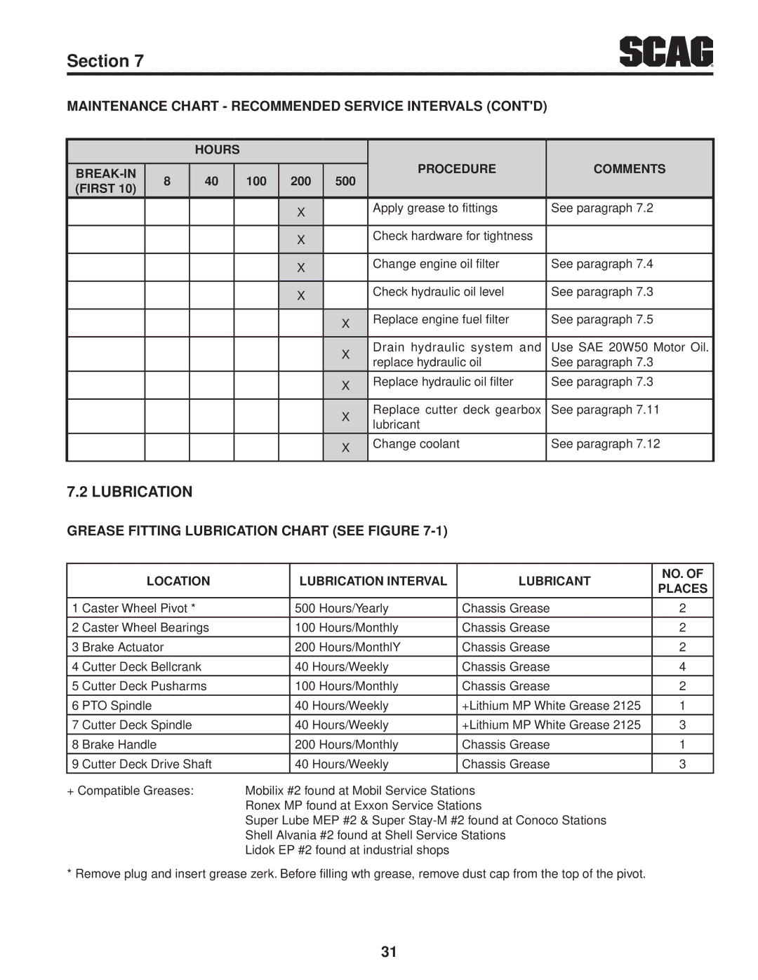
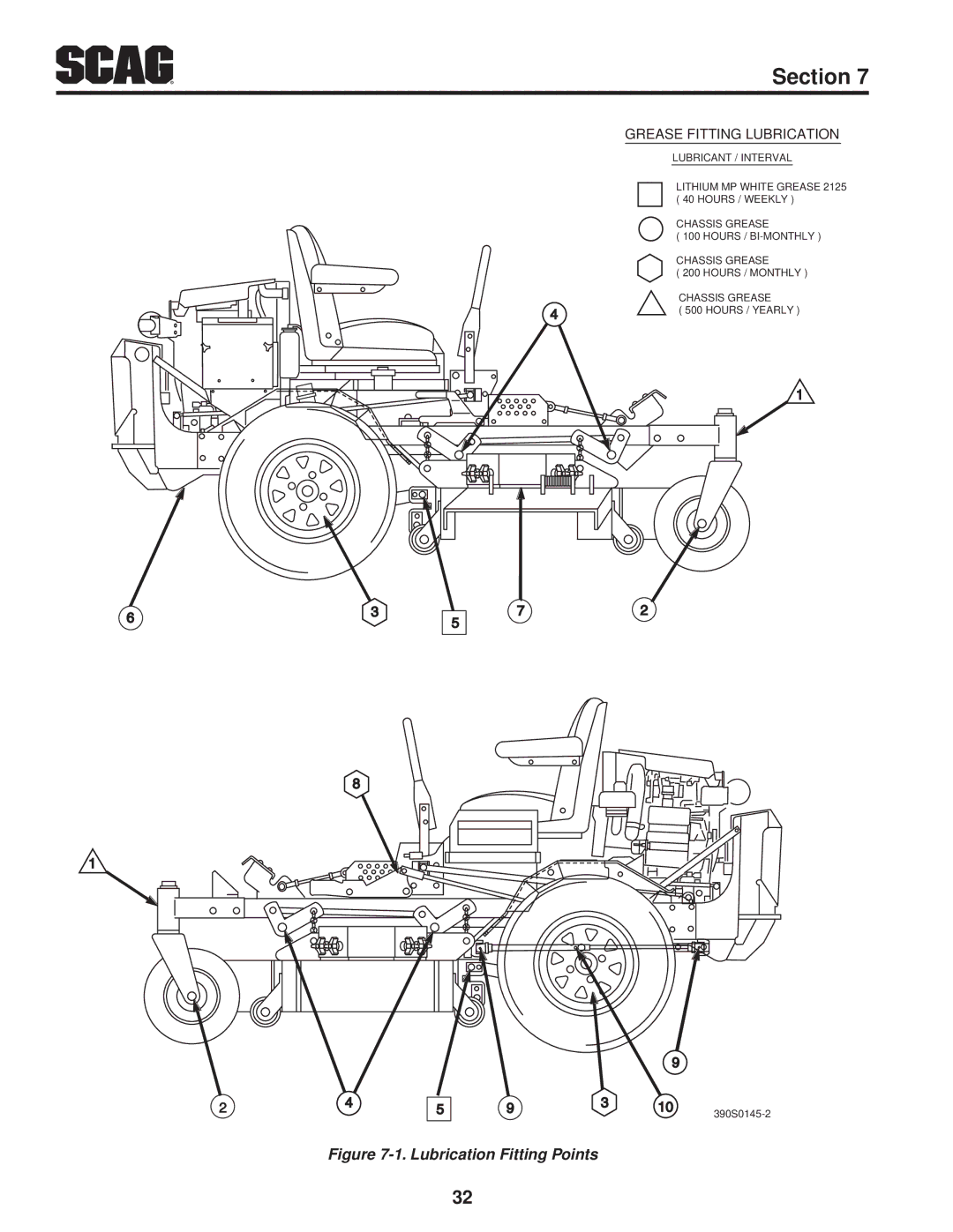
Scag Power Equipment STT61V-25KBD Operating Instructions, Controls and Instrument Identification

Page 16
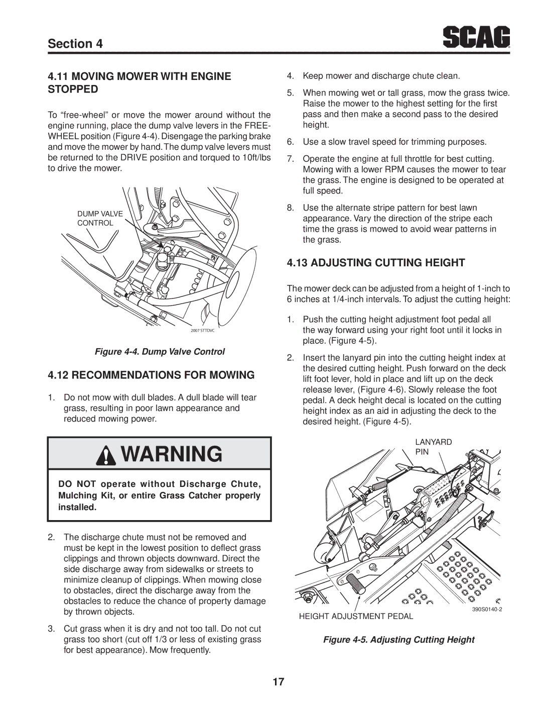
LEFT STEERING
CONTROL

R

Section 4

OPERATING INSTRUCTIONS

caution

Do not attempt to operate this mower unless you have read this manual. Learn the location and purpose of all controls and instruments before you operate this mower.

4.1CONTROLS AND INSTRUMENT IDENTIFICATION

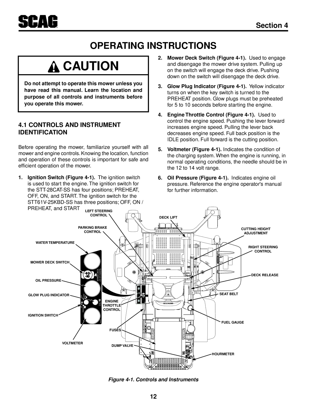
2.Mower Deck Switch (Figure 4-1). Used to engage and disengage the mower drive system. Pulling up on the switch will engage the deck drive. Pushing down on the switch will disengage the deck drive.

3.Glow Plug Indicator (Figure 4-1). Yellow indicator turns on when the key switch is turned to the PREHEAT position. Glow plugs must be preheated for 5 to 10 seconds before starting the engine.

4.Engine Throttle Control (Figure 4-1). Used to control the engine speed. Pushing the lever forward increases engine speed. Pulling the lever back decreases engine speed. Full back position is the IDLE position. Full forward is the cutting position.

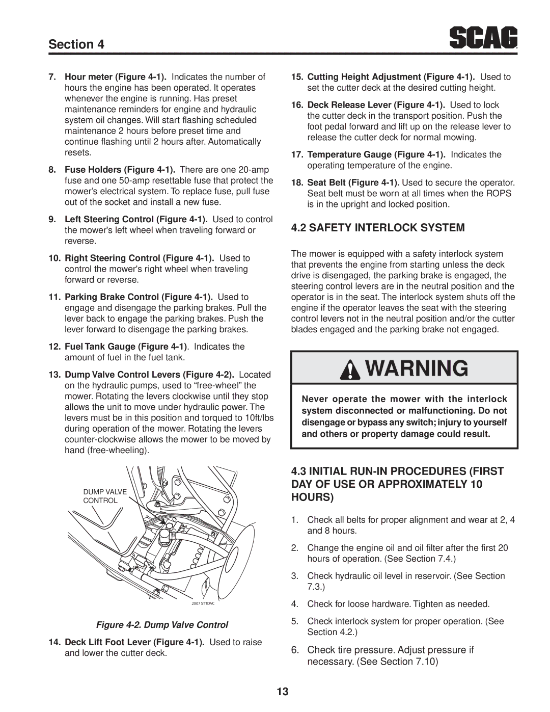
Before operating the mower, familiarize yourself with all mower and engine controls. Knowing the location, function and operation of these controls is important for safe and efficient operation of the mower.

1.Ignition Switch (Figure 4-1). The ignition switch is used to start the engine. The ignition switch for the STT-28CAT-SS has four positions; PREHEAT, OFF, ON, and START. The ignition switch for the STT61V-25KBD-SS has three positions; OFF, ON / PREHEAT, and START

5.Voltmeter (Figure 4-1).Indicates the condition of the charging system. When the engine is running, in normal operating conditions, the needle should be in the 12 to 14 volt range.

6.Oil Pressure (Figure 4-1). Indicates engine oil pressure. Reference the engine operator's manual for further information.

DECK LIFT

PARKING BRAKE

CONTROL

WATER TEMPERATURE

MOWER DECK SWITCH

OIL PRESSURE


MOWER DECK PULL OUT TO ENGAGE

PUSH IN TO DISENGAGE


GLOW PLUG INDICATOR

ON START


OFF PREHEAT

GLOW

PLUGS

ENGINE


THROTTLE


CONTROL

IGNITION SWITCH


C

CUTTING HEIGHT

ADJUSTMENT

RIGHT STEERING

CONTROL

DECK RELEASE

SEAT BELT

483762

FUSES

VOLTMETER

DUMP VALVE

FUEL GAUGE

HOURMETER

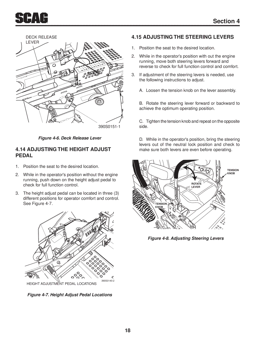
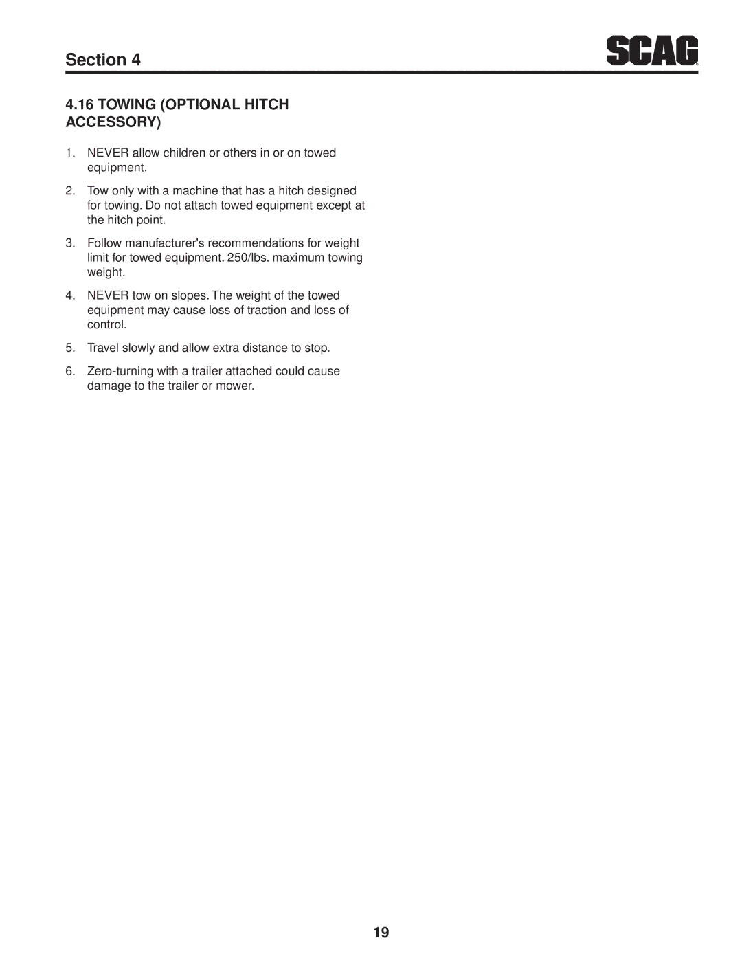
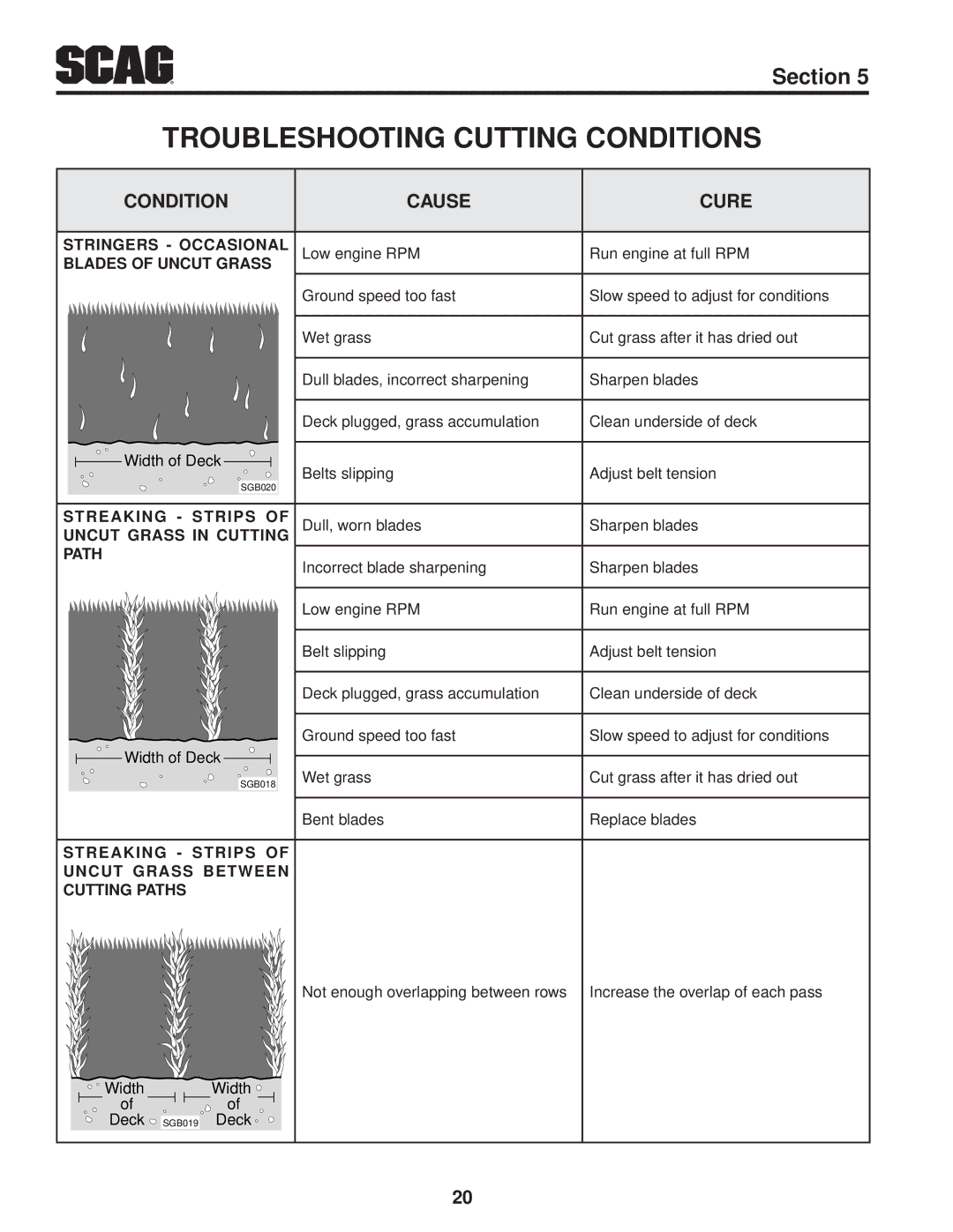
Figure 4-1. Controls and Instruments

12
Image 16
Contents OPERATOR’S Manual Remember Your Mower is only AS Safe AS the Operator STT61V-28CAT-SSTable of Contents Adjustments Parking Brake Adjustment Travel Adjustments General Information IntroductionDirection Reference Servicing The Engine and Drive TraiN ComponentsSymbols Symbol DescriptionSignal Words Safety InformationBefore Operation considerations Operation Considerations Section Roll-over protection system Foldable Roll-Over Protection SystemSeat Belt Inspection Maintenance Considerations & storage Using a spark arrestorSafety and Instructional Decals Diesel Fuel onlySpecifications Power headEngine ElectricalWeights and Dimensions Cutter DeckHydraulic System SMT61VOperating Instructions Controls and Instrument IdentificationSafety Interlock System Dump Valve ControlGround Travel and Steering Starting the EngineForward Travel Engaging the Deck Drive Cutter Blades Reverse TravelRotating Blades Hillside OperationParking the Mower After OperationMoving Mower with Engine Stopped Adjusting Cutting HeightRecommendations for Mowing Adjusting the Height Adjust Pedal Adjusting the Steering LeversTowing optional hitch accessory Troubleshooting Cutting Conditions Condition Cause CureTroubleshooting Cutting Conditions Contd Cut, or Rough ContourScalping Blades Hitting Adjustments Parking Brake AdjustmentTravel Adjustments Neutral AdjustmentBelt Adjustment Throttle Control and Choke AdjustmentsTracking Adjustment Cutter Deck Adjustments Belt AlignmentCutter Deck Level Cutter Deck PitchCutter Deck Height Cutter Deck StopCustom-Cut Baffle Adjustment Custom-Cut Baffle AdjustmentElectric clutch adjustment Clutch Air Gap AdjustmentMaintenance Maintenance Chart Recommended Service IntervalsMaintenance Chart Recommended Service Intervals Contd LubricationLubrication Fitting Points Checking Hydraulic Oil Level Changing Hydraulic OilEngine Oil Engine Fuel SystemBattery Engine Air CleanerCleaning and/or Replacing Air Cleaner Element Replacing In-Line Fuel Filter ElementsCharging the Battery Cutter BladesBlade Inspection Jump StartingTires Blade ReplacementBlade Sharpening Cutter Deck Gearbox Cooling SystemChecking Lubricant Level Changing LubricantBODY, DECK, and Upholstery Cleaning the Radiator Debris ScreenChecking The Fan Belt Tension Illustrated Parts List Scag Approved Attachments and AccessoriesIllustrated Parts List Section 61V & 72V Cutter Deck Description Cutter Deck Controls 481764 Link, Deck Lift Sheet Metal Components Sheet Metal Components Section STT ROLL-OVER Protection System with Suspension Seat 9292 Deck Drive Components Deck Drive Components Engine & Attaching Parts CAT Diesel Available through the individual engine manufacturer Radiator & Attaching Parts CAT Diesel Radiator & Attaching Parts CAT Diesel Engine & Attaching Parts Kubota Diesel 424633 Latch, Hood Brake and Steering Components Brake and Steering Components Fuel and Hydraulic System CAT Diesel Fuel and Hydraulic System CAT Diesel Fuel and Hydraulic System Kubota Diesel Hose Assy, 1/2 ID Tank to Filter Base Section BDP-16A Hydraulic Pump Assembly with Cooling Fan Hex Screw, Flanged Head M10 x 1.50-65mm Electrical System CAT Diesel Electrical System CAT Diesel Electrical System Kubota Diesel 483643 Cover, Sealed Single 483641 Replacement Decals and Information Plates Manufactured Under ONE or MoreSttkbd Decals Page2 Electrical Schematic CAT Diesel COMElectrical Schematic Kubota Diesel Glow Plug POS NEG Volt Meter PTO Switch Module RelayLimited Warranty Commercial Equipment