Eiki lc-sb15 owner manual Video System Selection, Auto, AV System Menu Video or S-Video

Page 34

Video Input

Video System Selection

1Press the MENU button and the On-Screen Menu will appear. Press the Point Left/Right button to move the red frame pointer to the AV System Menu icon.

2Press the Point Down button to move the red arrow pointer to the system that you want to select and then press the SELECT button.

Video or S-Video

Auto

The projector automatically detects incoming video system, and adjusts itself to optimize its performance.

When Video System is PAL-M or PAL-N, select system manually.

PAL / SECAM / NTSC / NTSC4.43 / PAL-M / PAL-N

If the projector cannot reproduce proper video image, it is necessary to select a specific broadcast signal format among PAL, SECAM, NTSC, NTSC 4.43, PAL-M, and PAL-N.

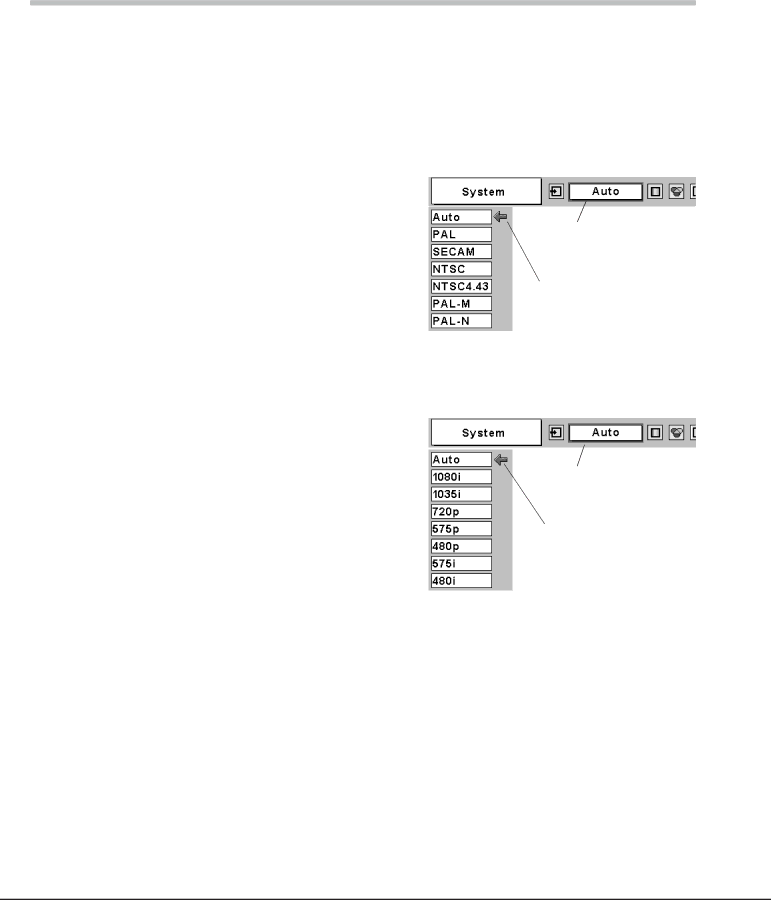
AV System Menu (Video or S-Video)

AV System Menu icon

This box indicates the system being selected.

Move the pointer to a system and press the SELECT button.

Component

Auto

The projector automatically detects incoming video signal, and adjusts itself to optimize its performance.

COMPONENT VIDEO SIGNAL FORMAT

If the projector cannot reproduce proper video image, it is necessary to select a specific component video signal format among 480i, 575i, 480p, 575p, 720p, 1035i, and 1080i.

AV System Menu (Component)

AV System Menu icon

This box indicates the system being selected.

Move the pointer to a system and press the SELECT button.

NOTE

The AV System Menu cannot be selected when selecting RGB(Scart).

34

Image 34
Contents Model LC-SB15 Table of Contents To the Owner Risk of Electric Shock Do not OpenSafety Instructions Voor de klanten in NederlandAir Circulation Safety InstructionsInstalling the Projector in Proper Position Moving the ProjectorCompliance Federal Communication Commission NoticeFor the U.S.A. and Canada ComplianceFor Continental Europe 200 240 V ACFeatures and Design Back Part Names and FunctionsFront BottomPart Names and Functions TerminalTop Ui oRemote Control Signal Emission indicatorLaser Pointer Function Pointer FunctionRemote Control Code Wireless Mouse OperationRemote Control Operating Range Remote Control Batteries InstallationAdjustable Feet InstallationPositioning the Projector Installation Connecting to a ComputerTerminals Connecting to Video EquipmentProjector Turning On the Projector Basic OperationTurning Off the Projector Keystone Adjustment Zoom AdjustmentFocus Adjustment Basic OperationNo Show Function Timer FunctionSound Adjustment Direct OperationTop Control Remote ControlOn-Screen Menu On-Screen MenuMenu Bar Input Source Selection Computer InputRGB Auto Computer InputComputer System Selection ModeTo store adjustment data Computer Adjustment AutoPC Adjust Menu Auto PC AdjComputer Adjustment Manual Display area To store adjustment data ResetMode free To clear adjustment dataImage Level Selection Image Level Adjustment Screen Size Adjustment Input button Video Computer Video button Video Video InputInput Source Selection Video, S-Video Source Select Menu VideoComponent Video InputInput Source Selection Component, RGB Scart 21-Pin RGB ScartAuto Video System SelectionVideo or S-Video AV System Menu Video or S-VideoCinema Image button Standard CinemaTint ColorProgressive Resets all adjustment to their previous figure Setting SettingSetting To change the code for the remote control To change the code for the projectorTOP Control Maintenance and CleaningProjector is shut down and the Warning indicator lights red Then check the items belowCleaning the Projection Lens Maintenance and CleaningCleaning the Air Filters Cleaning the Projector CabinetLamp Replacement Reset the Lamp replace counterWhen the lamp replace counter is reset, the Lamp Lamp Replace CounterTroubleshooting AppendixAppendix Indicators and Projector Condition Projector is OFF. The AC power cord is unpluggedMenu Tree PC AdjustImage Select Image Adjust Screen InputImage Adjust Screen Sound SettingImage Select Freq Compatible Computer SpecificationsResolution KHzTechnical Specifications Terminal DVI-I Pin Configuration Configurations of TerminalsTerminal HDB15-PIN Pin Configuration DVI-I Terminal DIGITAL/ANALOGPOA-MACAP Service Port ConnectorOptional Parts KA-DV20Attaching the Lens Cover Page Key to better communications Canada