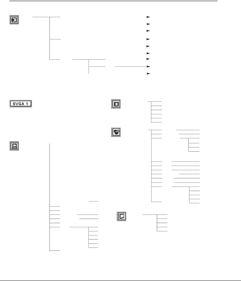
Eiki lc-sb15 owner manual Menu Tree, Input, System, PC Adjust, Image Select Image Adjust Screen

Page 48

Appendix

Menu Tree

Computer Input / Video Input

Input

Computer 1

Computer 2

Video


RGB( Analog )


Go to System (1)


N/A


RGB( PC Digital )


N/A


RGB( AV HDCP )


Go to System (1)


RGB


Go to System (2)


Component


RGB( Scart )


N/A


Go to System (3)


Auto


Go to System (3)


Video


Go to System (3)


S-Video


N/A - - - not applicable

Computer Input

System (1)


MODE 1


MODE 2


SVGA 1


- - - -


Systems displayed in the System Menu vary depending on an input signal.

PC Adjust


Auto PC Adj.


Fine sync.


Total dots


Horizontal


Vertical


Current mode


Clamp


Display area


Display area - H

Display area - V

Full screen

Reset

Mode free

Store

Quit

0 - 31

640 x 480

720 x 400

800 x 600

1024 x 768

1152 x 864

1280 x 1024

1400 x 1050 Quit

On / Off

Yes / No

Mode 1

Mode 2

Mode 3

Mode 4

Mode 5

Quit

Image Select

Image Adjust

Screen

Standard

Real

Image 1

Image 2

Image 3

Image 4

Contrast

Brightness

Color Temp

Red

Green

Blue

Sharpness

Gamma

Reset

Store

Quit

Normal

True

Wide

Digital zoom +

Digital zoom –

0 - 63

0 - 63 High Mid

Low

XLow

0 - 63

0 - 63

0 - 63

0 - 15

0 - 15 Yes / No Image 1 Image 2 Image 3 Image 4 Quit

48

Image 48
Contents Model LC-SB15 Table of Contents To the Owner Risk of Electric Shock Do not OpenSafety Instructions Voor de klanten in NederlandSafety Instructions Installing the Projector in Proper PositionAir Circulation Moving the ProjectorCompliance Federal Communication Commission NoticeCompliance For Continental EuropeFor the U.S.A. and Canada 200 240 V ACFeatures and Design Part Names and Functions FrontBack BottomPart Names and Functions TerminalTop Ui oRemote Control Signal Emission indicatorLaser Pointer Function Pointer FunctionRemote Control Code Wireless Mouse OperationRemote Control Operating Range Remote Control Batteries InstallationInstallation Adjustable FeetPositioning the Projector Installation Connecting to a ComputerConnecting to Video Equipment TerminalsProjector Basic Operation Turning On the ProjectorTurning Off the Projector Zoom Adjustment Focus AdjustmentKeystone Adjustment Basic OperationTimer Function Sound AdjustmentNo Show Function Direct OperationRemote Control On-Screen MenuTop Control On-Screen MenuMenu Bar Computer Input Input Source SelectionRGB Computer Input Computer System SelectionAuto ModeComputer Adjustment Auto PC Adjust MenuTo store adjustment data Auto PC AdjComputer Adjustment Manual Reset Mode freeDisplay area To store adjustment data To clear adjustment dataImage Level Selection Image Level Adjustment Screen Size Adjustment Video Input Input Source Selection Video, S-VideoInput button Video Computer Video button Video Source Select Menu VideoVideo Input Input Source Selection Component, RGB Scart 21-PinComponent RGB ScartVideo System Selection Video or S-VideoAuto AV System Menu Video or S-VideoCinema Image button Standard CinemaColor TintProgressive Resets all adjustment to their previous figure Setting SettingSetting To change the code for the remote control To change the code for the projectorMaintenance and Cleaning Projector is shut down and the Warning indicator lights redTOP Control Then check the items belowMaintenance and Cleaning Cleaning the Air FiltersCleaning the Projection Lens Cleaning the Projector CabinetLamp Replacement Reset the Lamp replace counterWhen the lamp replace counter is reset, the Lamp Lamp Replace CounterTroubleshooting AppendixAppendix Indicators and Projector Condition Projector is OFF. The AC power cord is unpluggedPC Adjust Image Select Image Adjust ScreenMenu Tree InputSound Setting Image Adjust ScreenImage Select Compatible Computer Specifications ResolutionFreq KHzTechnical Specifications Configurations of Terminals Terminal HDB15-PIN Pin ConfigurationTerminal DVI-I Pin Configuration DVI-I Terminal DIGITAL/ANALOGService Port Connector Optional PartsPOA-MACAP KA-DV20Attaching the Lens Cover Page Key to better communications Canada