Emerson 240V, 208 Cable Installation, Wiring Preparation, Configuring the Bypass Voltage TB2

Page 15

Installation

2.3Cable Installation

2.3.1 Wiring Preparation

! WARNING

Please read this section thoroughly before attempting to install wiring to this unit.

This UPS should be installed by a qualified / certified electrician.

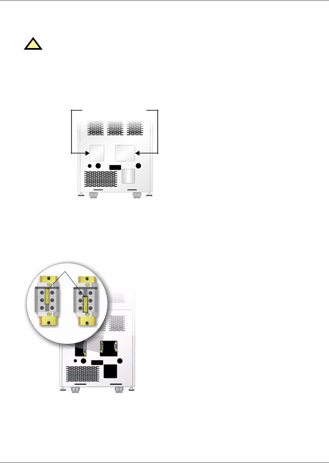
Removing the Cover Plates

Customer-Provided Overcurrent Protection

A branch rated overcurrent protection device (cir- cuit breaker or fused disconnect switch) must be installed for the AC input.

If the start-up is on bypass, the UPS has a six- cycle inrush current that is up to 20 times the rated output current. This must be taken into account when selecting the overload protection device at the AC input supply distribution point. To avoid random tripping on start-up, it is recom-

On the back of the UPS, cover plates are over the input and output terminals, as shown at right. Keep screws and plates to one side.

Remove Cover Plates

mended that the AC input supply be protected with a circuit breaker capable of withstanding this initial inrush.

This UPS is fitted with EMI suppression filters. Earth leakage current is less than 40mA. Tran- sient and steady state earth leakage currents may occur when starting the equipment. This should be taken into account when selecting ground cur- rent detection devices, as the earth leakage cur- rents of both the UPS and load will be carried.

Input and output cables must be run in separate conduits.

Configuring the Bypass Voltage (TB2)

The UPS voltage is factory-set to 208 V. Should the user have a utility supply of 240 V, the bypass voltage jumper will have to be changed to ensure correct output voltage. After selection, retorque jumper screws to

28in-lb.

Bypass Voltage Jumper


OR

208 V

240 V

(default)


11

Image 15
Contents Nfinity Power System Page Table of Contents Figures Important Safety Instructions Glossary of Symbols Standard Components FeaturesGeneral Description System DescriptionFront and back views Nfinity weight and dimensionsBypass Mode Normal ModeBackup Mode Auto Restart ModeSystem Control Module Major ComponentsUnit Frame User Interface ModuleBattery Module Power ModuleSite Preparation Required Setup EquipmentInspection EnvironmentUnloading the UPS UnloadingStationary Mounting Cable Installation Wiring PreparationConfiguring the Bypass Voltage TB2 Input Wiring TB1 Output Wiring TB3Grounding Conductor Installation Bypass Voltage Jumper Position TB2 Connecting to External Panel Boards208 VAC Setup 1 208 VACSetup 2 120 VAC Setup 3 240 VACRepo Connection Repo switch connectionsCOM2 Serial CommunicationsCOM Ports COM1 Relay ContactsButtons Controls and IndicatorsFault/Warning and Status LEDs Display ControlsNavigating the Menu Status LED ModesShutting Down the UPS Operating ProceduresStart-Up and Initialization Manual Transfer to BypassDisplay Date/Time UPS Status Event Log Module ReplacementUPS Configuration Active Alarms Service Tools Main MenuUPS Status Screen UPS Configuration Screen Review Settings Change Settings Change Configuration Settings Change Settings MenuStart Day Auto Restart ModeAuto Restart Delay IntervalThreshold DST ModeAlarm Mode Set Date/TimeGuarantee Shutdown Enable UPS Configuration Screen Service Mode Menu Service ModeDisplay Date/Time Active Alarms Event LogTransfer to Bypass Module Replacement Clear Failures Service Tools for Liebert Global Services EngineersUser Interface Text Cause Action Active AlarmsOperation Control Module Power ModuleBattery Module Guide to LEDs Module LED IndicationRemoving Modules Module ReplacementReplacing the User Interface Adding or Replacing ModulesReplacing Fan Filters MaintenanceScheduled Maintenance Proper CareSpecifications Product Warranty RegistrationSpecifications Page Technical Support/Service Company Behind the ProductsLocations