Rackmount Solutions RP-117QD Alarm I/O, VCR Connection for Tape Recording Start and Stop Control

Page 33

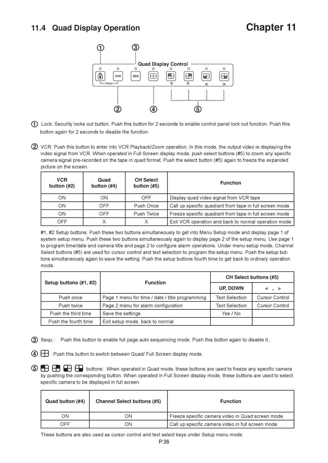
11.2 ALARM I/O Connection & Operation

Chapter 11

1. ALARM I/O :

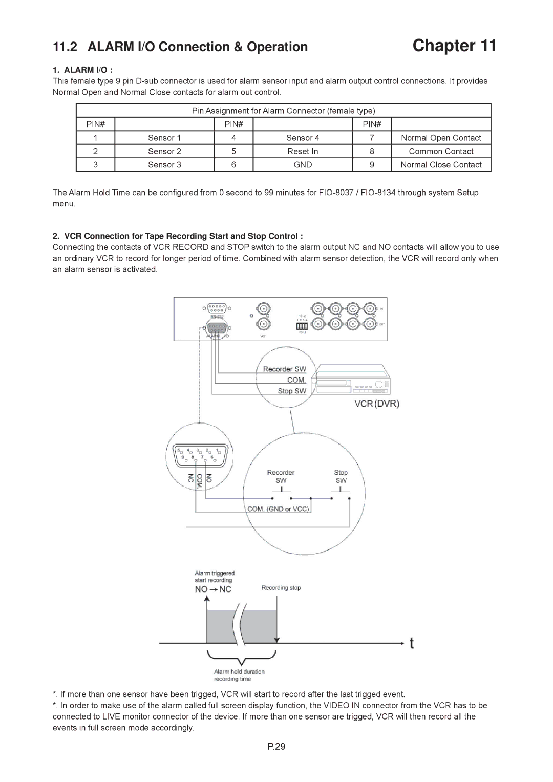
This female type 9 pin D-sub connector is used for alarm sensor input and alarm output control connections. It provides Normal Open and Normal Close contacts for alarm out control.

Pin Assignment for Alarm Connector (female type)

PIN#


PIN#


PIN#


1

Sensor 1

4

Sensor 4

7

Normal Open Contact

2

Sensor 2

5

Reset In

8

Common Contact

3

Sensor 3

6

GND

9

Normal Close Contact

The Alarm Hold Time can be configured from 0 second to 99 minutes for FIO-8037 / FIO-8134 through system Setup menu.

2. VCR Connection for Tape Recording Start and Stop Control :

Connecting the contacts of VCR RECORD and STOP switch to the alarm output NC and NO contacts will allow you to use an ordinary VCR to record for longer period of time. Combined with alarm sensor detection, the VCR will record only when an alarm sensor is activated.

*. If more than one sensor have been trigged, VCR will start to record after the last trigged event.

*. In order to make use of the alarm called full screen display function, the VIDEO IN connector from the VCR has to be connected to LIVE monitor connector of the device. If more than one sensor are trigged, VCR will then record all the events in full screen mode accordingly.

P.29
Image 33
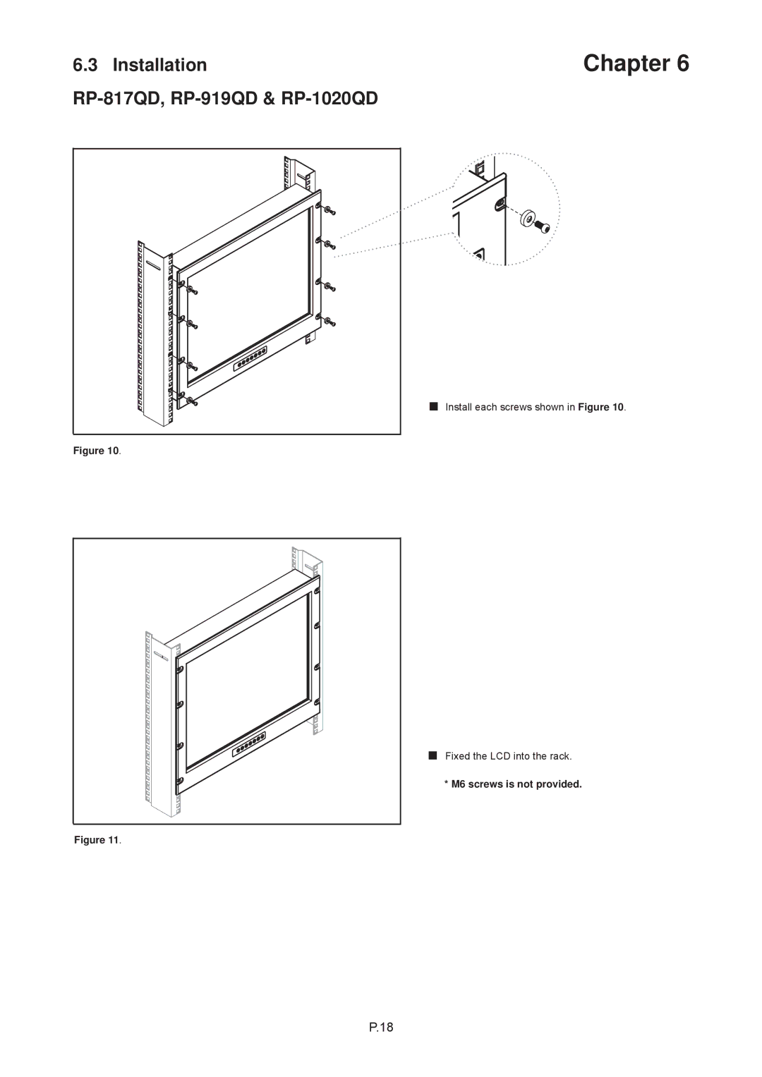
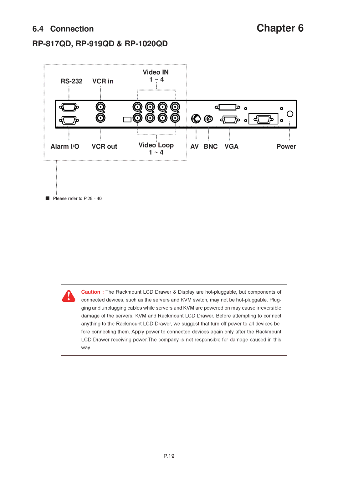
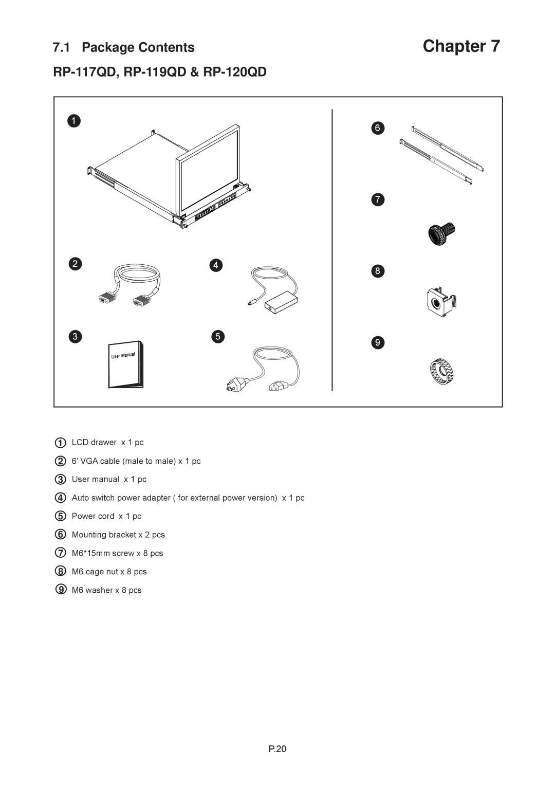
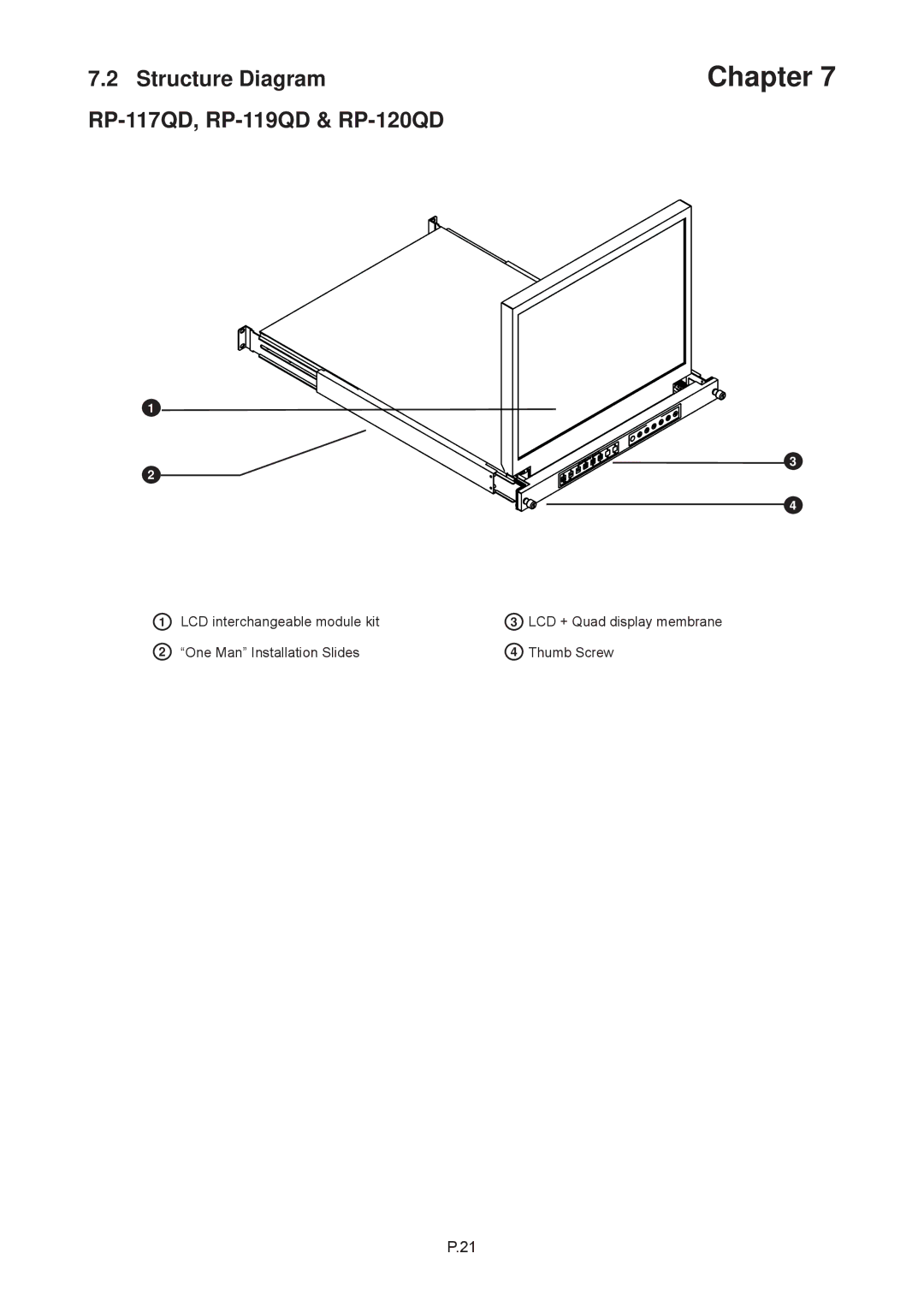
Contents Page RP-W119QD Part 2 43 LCD Quad Display RP-817QD, RP-919QD & RP-1020QD Blank Chapter Page Before Installation Matrix DB-15 KVM Matrix Cat6 KVMCombo Cat6 KVM Combo DB-15 KVMPackage Contents Structure Diagram RP-W819QD & RP-W922QD RP-W819QD RP-W922QD Connection RP-W819QD & RP-W922QD RP-W119QD LCD interchangeable module kit One Man Installation Slides Thumb ScrewHow to Use the Slides RP-W119QD Connection LCD Specifications RP-W922QD, RP-W819QD & RP-W119QD D x H RP-817QD, RP-919QD & RP-1020QD Structure Diagram RP-817QD, RP-919QD & RP-1020QD Installation RP-817QD, RP-919QD & RP-1020QD Connection RP-817QD, RP-919QD & RP-1020QD RP-117QD, RP-119QD & RP-120QD Structure Diagram RP-117QD, RP-119QD & RP-120QD How to Use the Slides RP-117QD, RP-119QD & RP-120QD Connection LCD Specifications RP117QD series D x H WeightMembrane For LCD OSD MenuOn-screen Menu VCR Ch1 In, Ch2 In, Ch3 In, and Ch4 In Video in connectorsVCR out TerminationsVCR Connection for Tape Recording Start and Stop Control Alarm I/OVideo Loss Alarm Sensor Activated AlarmChapter 3 4 Pin assignment of the male type 9 pin D-sub connectorXX-DF Channel Select Byte Start Stop StartChapter Quad Display Control Setup buttons #1, #2 Function CH Select buttons #5Quad CH Select Function Button #2 Button #4 Button #5 Quad button #4 Channel Select buttons #5 FunctionTitle setup 1 of the Setup Menu Display SettingDwell Time setup TIME/DATE setupAlarm Hold Duration 2 of the setup menu- Alarm SettingLoss Alarm Save the settings and exit Setup Menu modeFull Screen Display Mode Quad Display ModeStill Frame Display Mode Auto-Sequence ModeVCR Operations Input rating Output ratingEfficiency Troubleshooting Blank