Rackmount Solutions RP-W819QD manual Part 2 43 LCD Quad Display RP-817QD, RP-919QD & RP-1020QD

Page 3

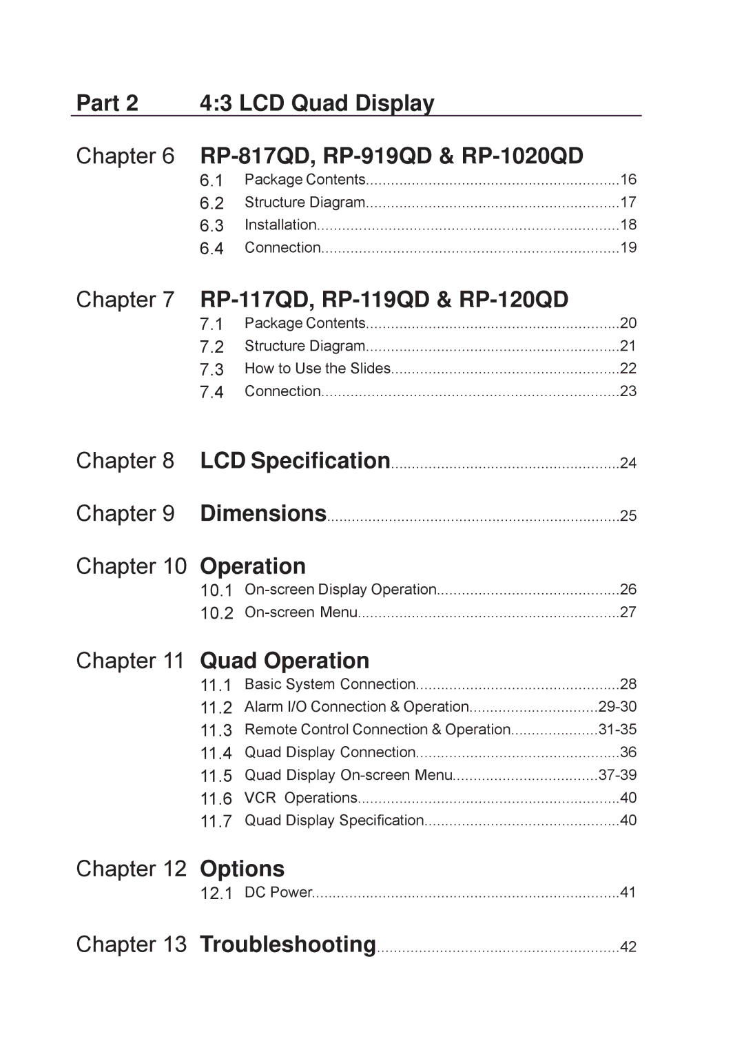
Part 2 4:3 LCD Quad Display

Chapter 6 RP-817QD, RP-919QD & RP-1020QD


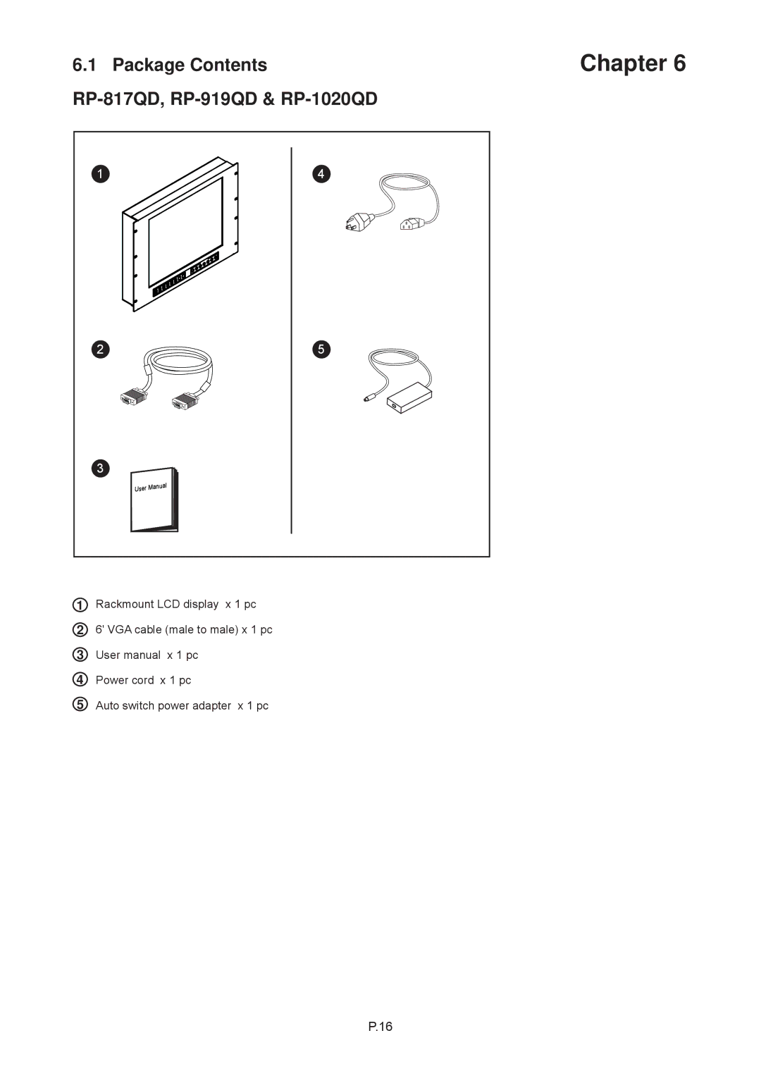
6.1

Package Contents

16

6.2

Structure Diagram

17

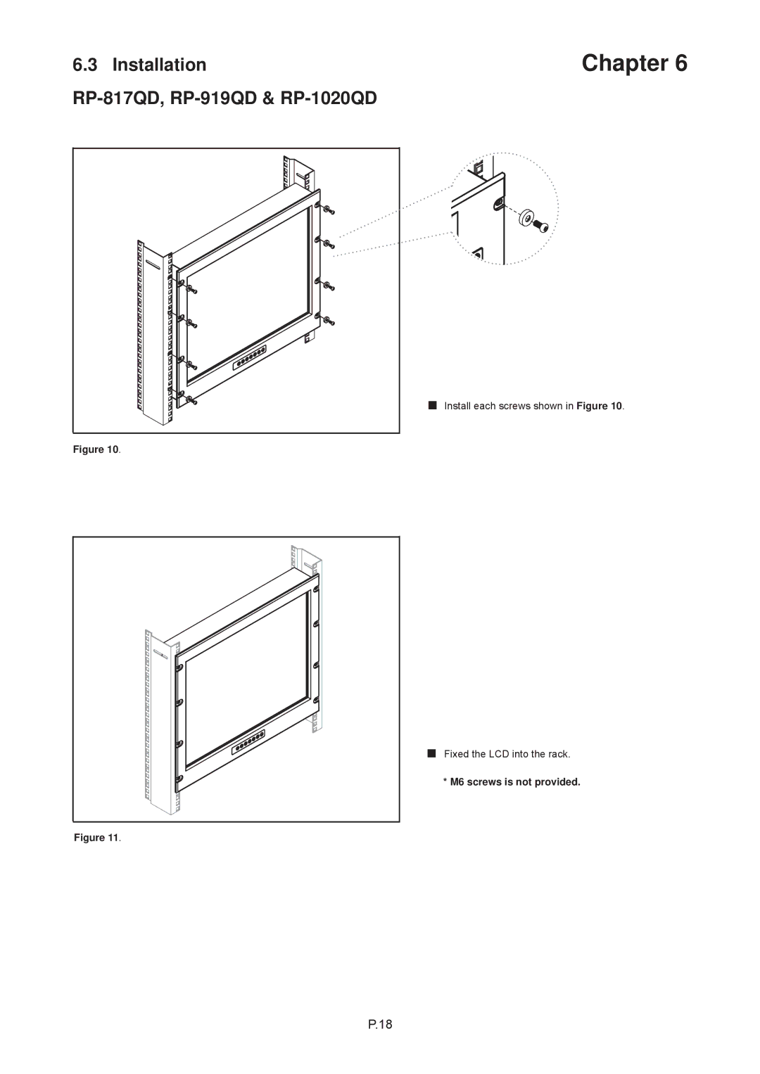
6.3

Installation

18

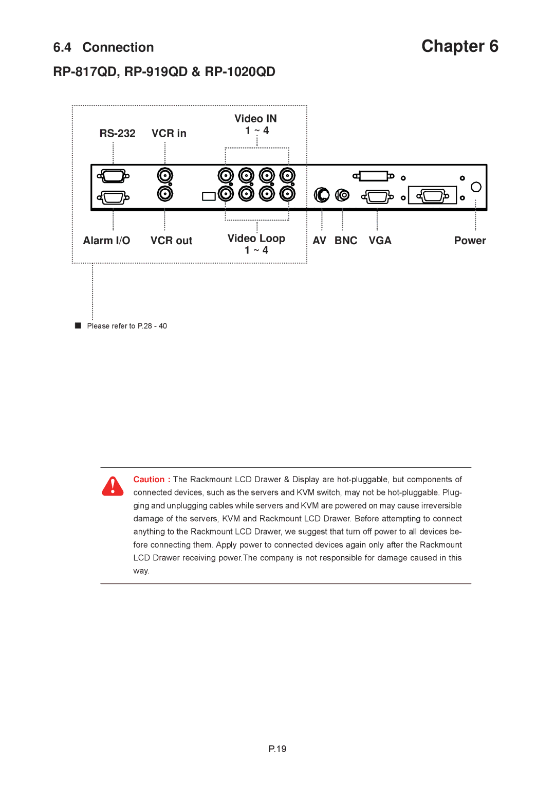
6.4

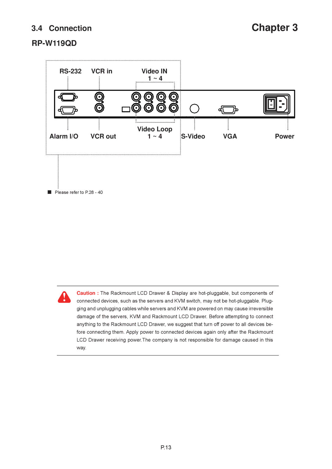
Connection

19

Chapter 7

RP-117QD, RP-119QD & RP-120QD


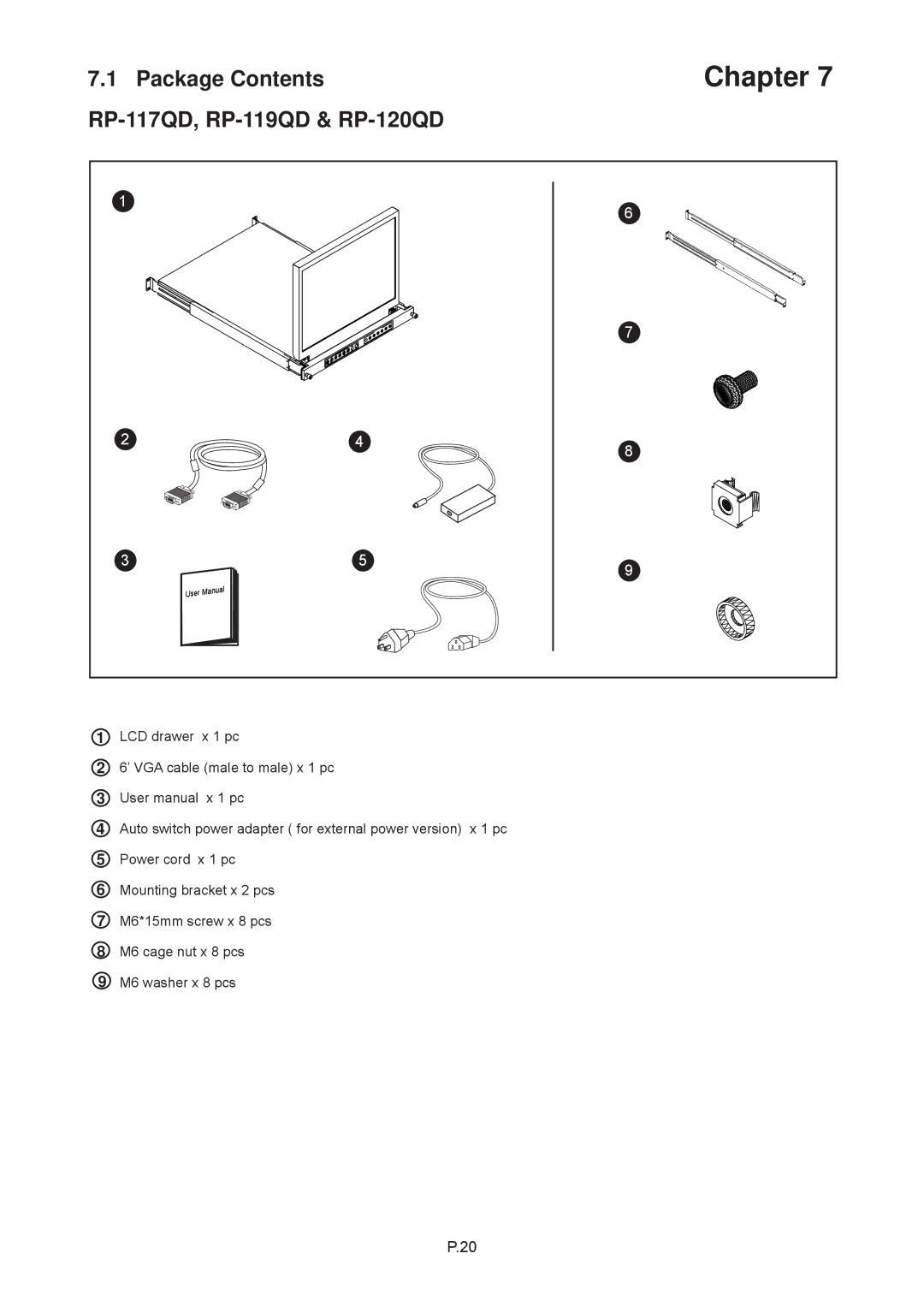
7.1

Package Contents

20


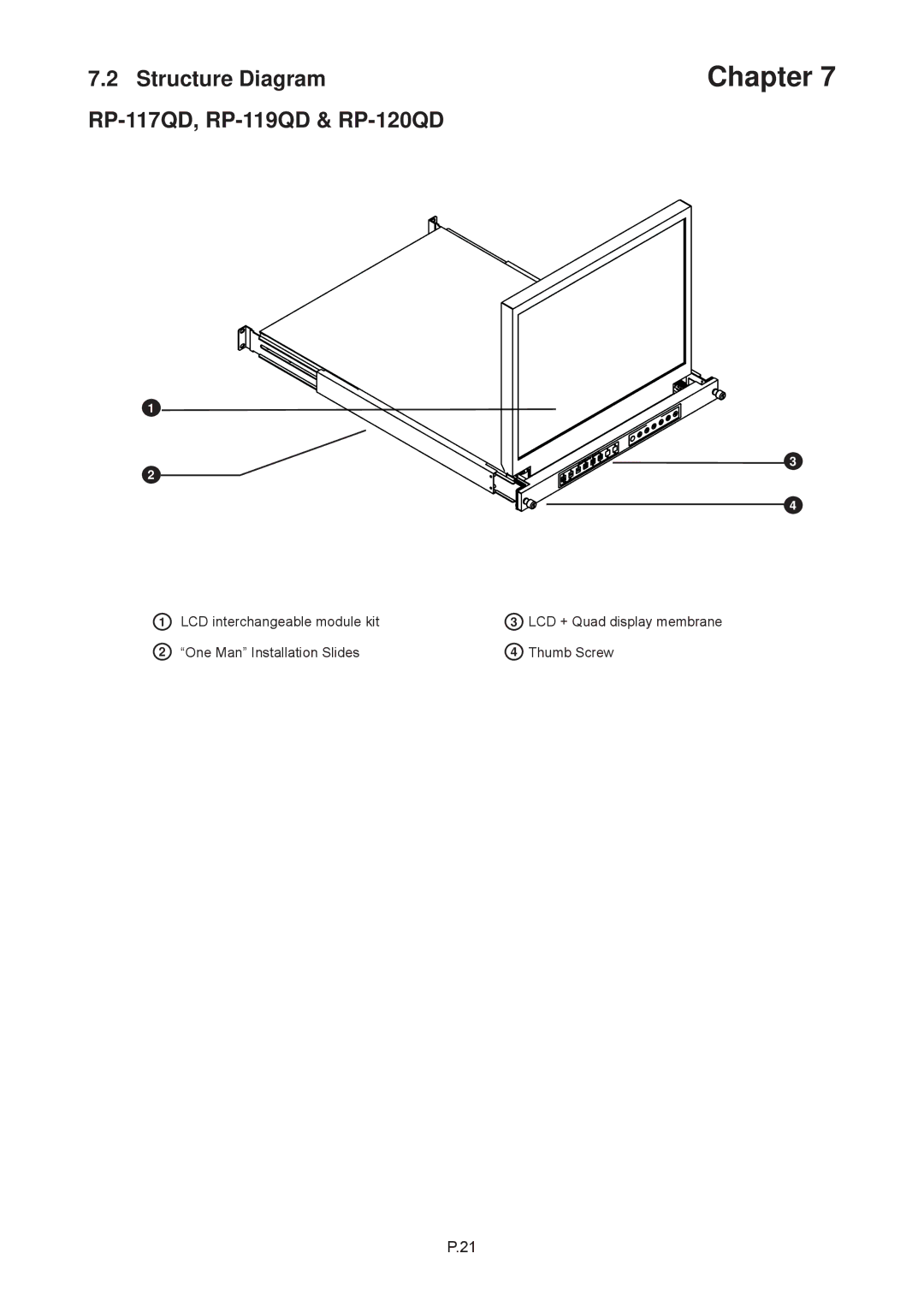
7.2

Structure Diagram

21


7.3

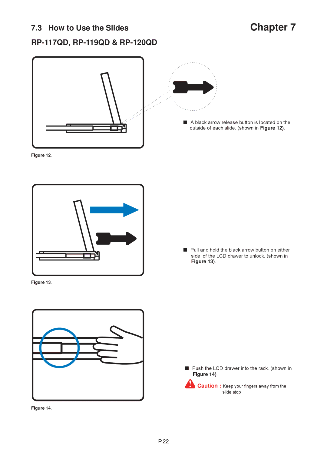
How to Use the Slides

22


7.4

Connection

23

Chapter 8

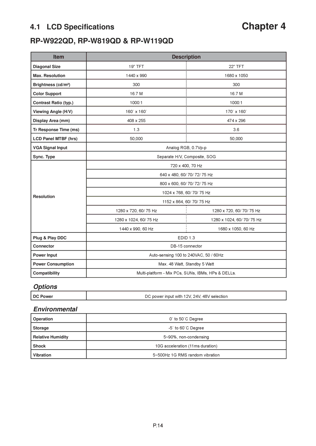
LCD Specification

24

Chapter 9

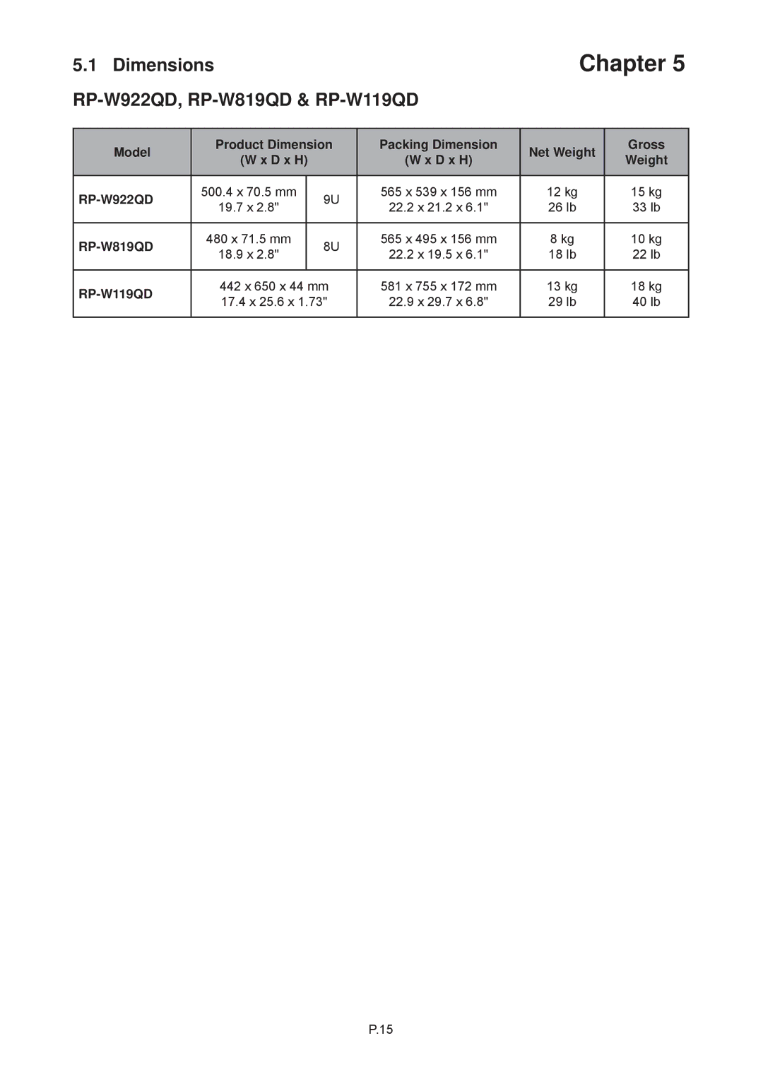
Dimensions

25

Chapter 10

Operation


10.1

On-screen Display Operation

26


10.2

On-screen Menu

27

Chapter 11

Quad Operation


11.1

Basic System Connection

28


11.2

Alarm I/O Connection & Operation

29-30


11.3

Remote Control Connection & Operation

31-35


11.4

Quad Display Connection

36


11.5

Quad Display On-screen Menu

37-39


11.6

VCR Operations

40


11.7

Quad Display Specification

40

Chapter 12

Options


12.1

DC Power

41

Chapter 13 Troubleshooting

42

Image 3
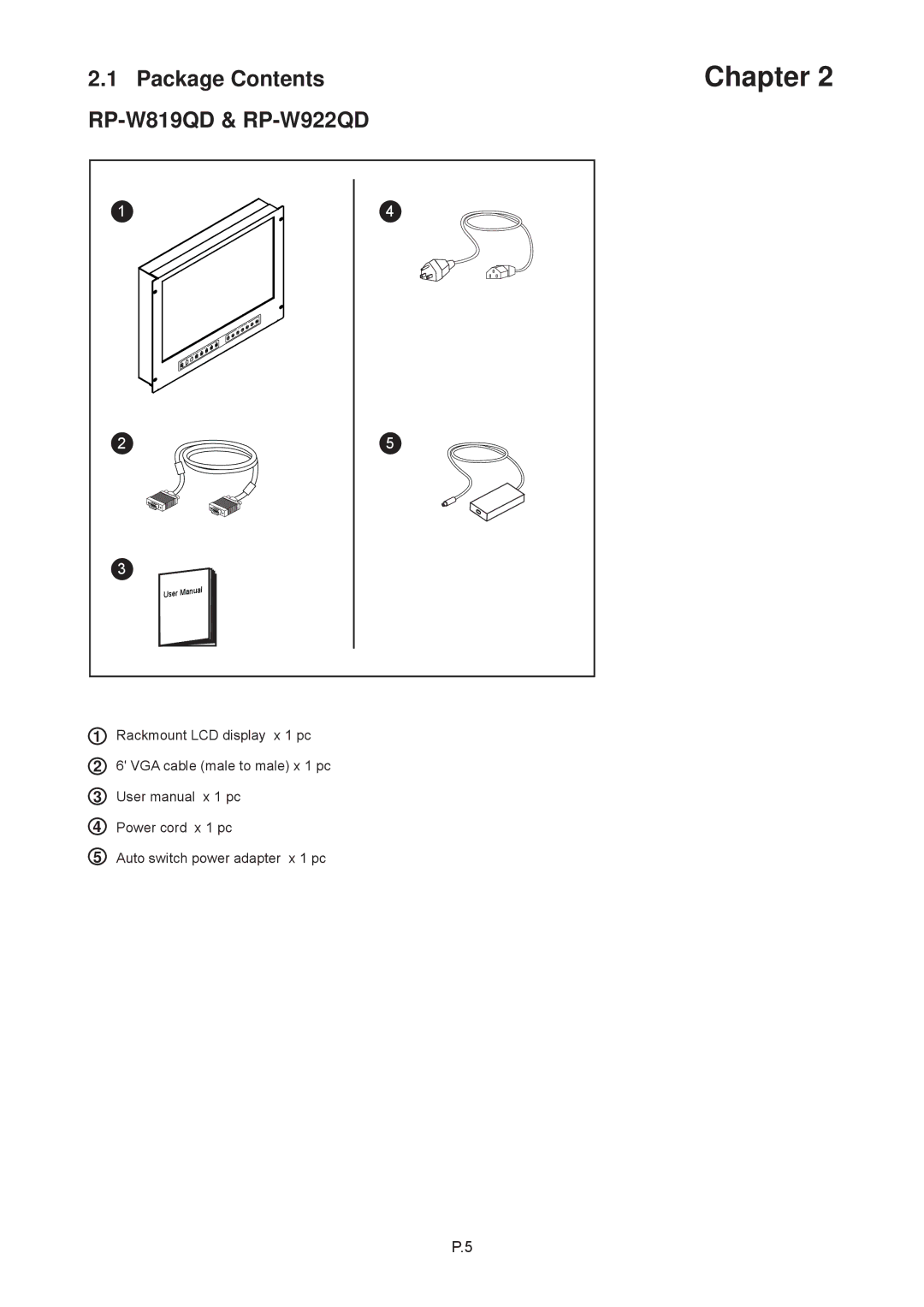
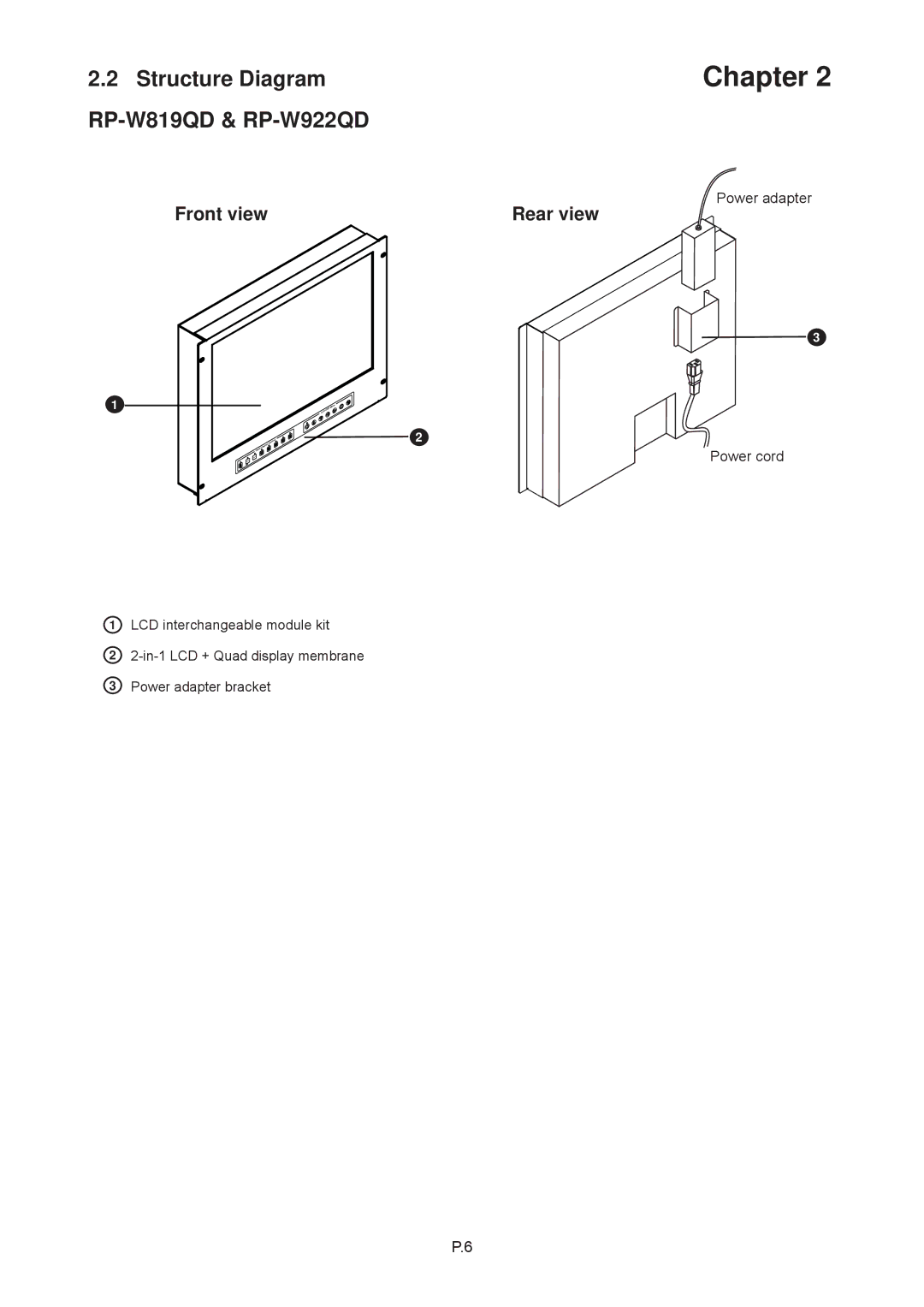
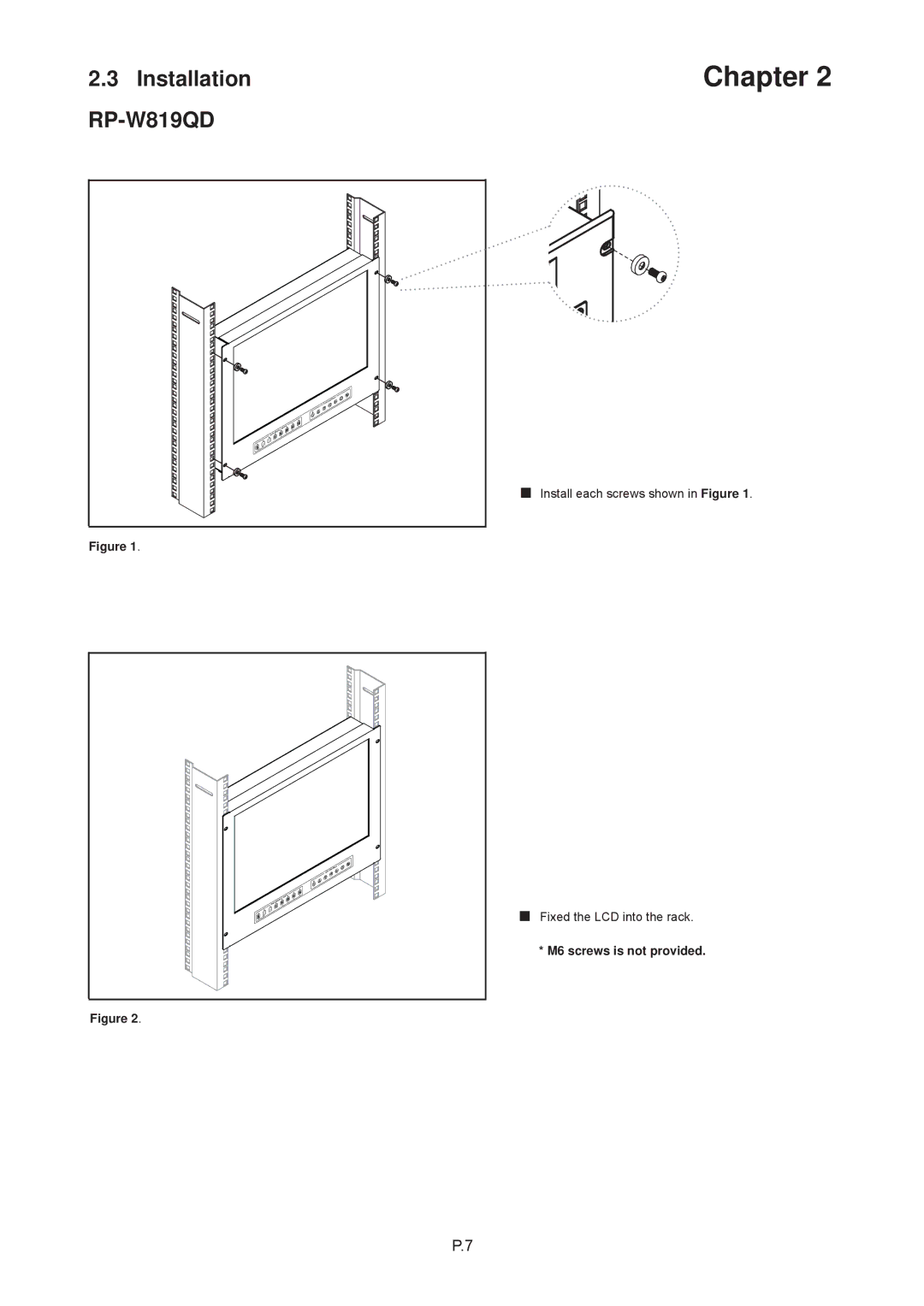
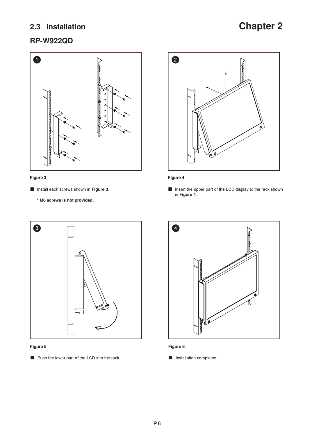
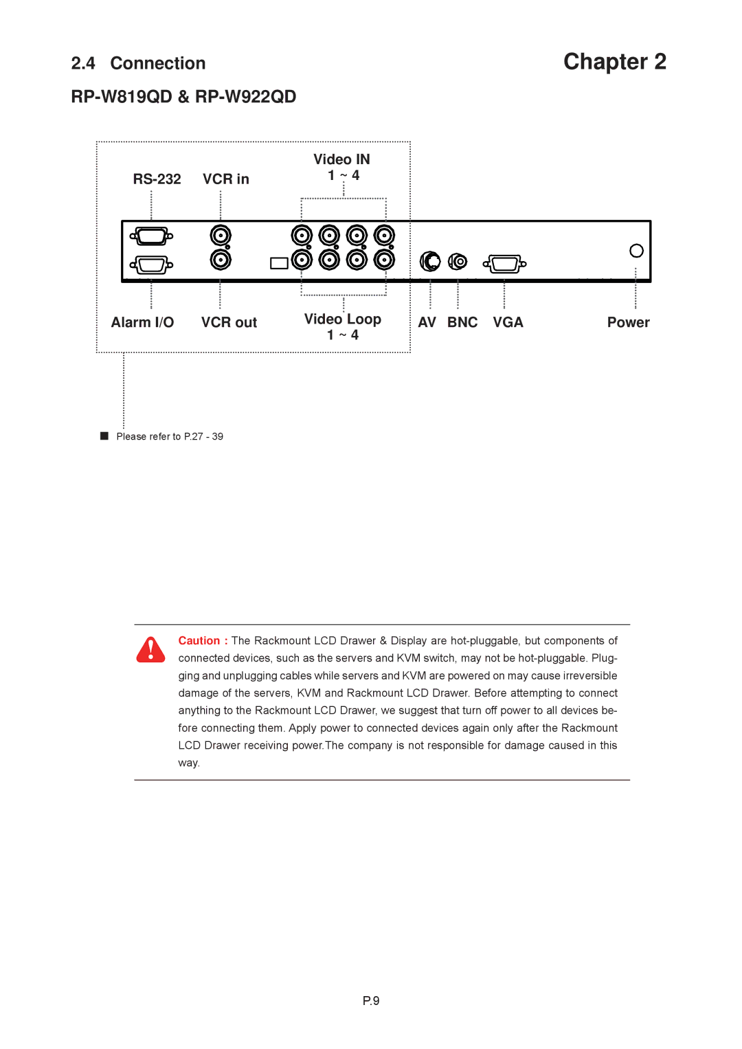
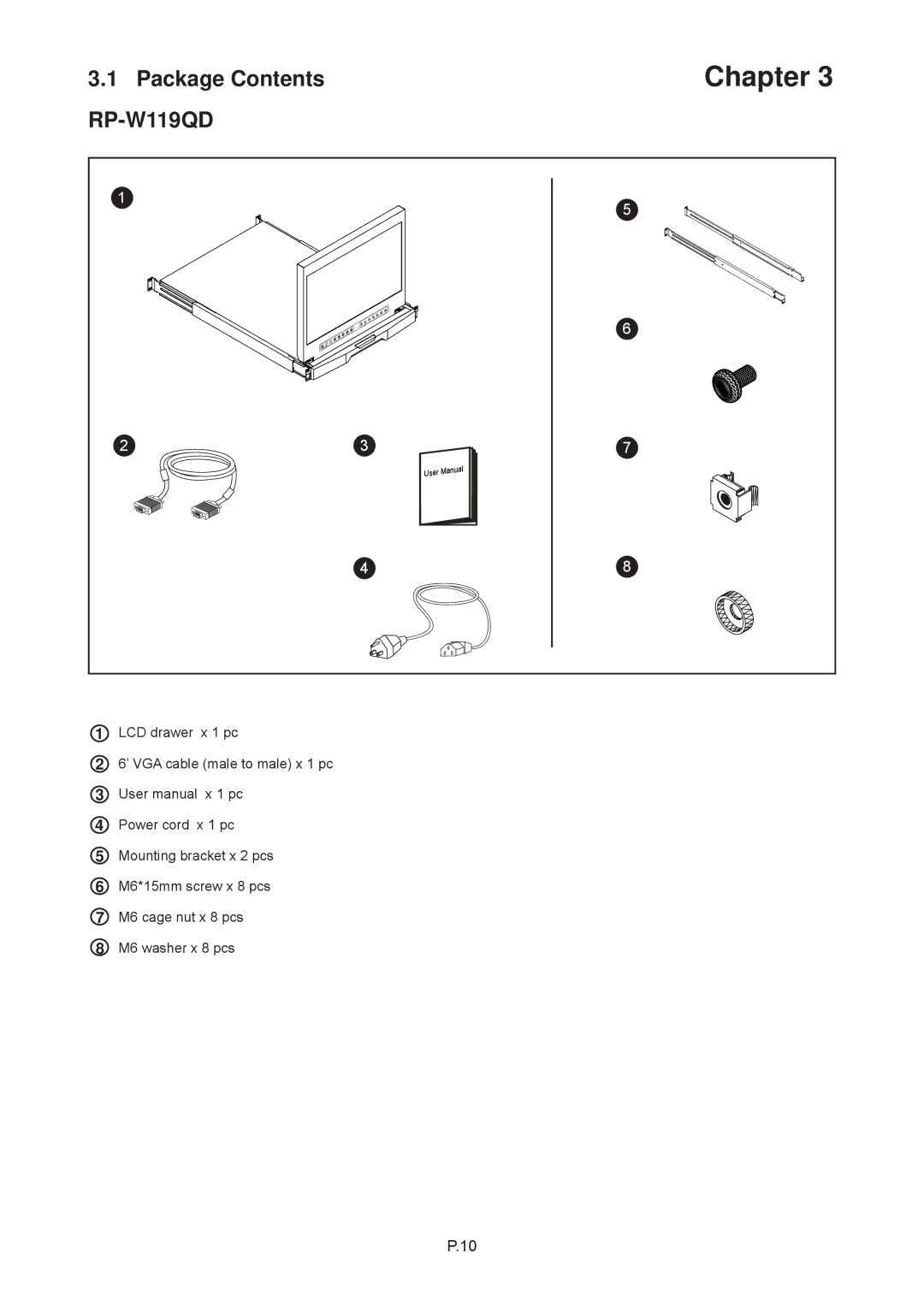
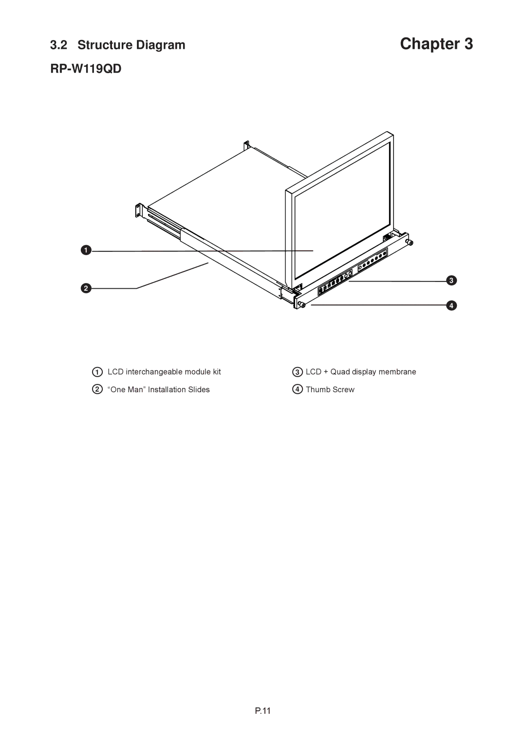
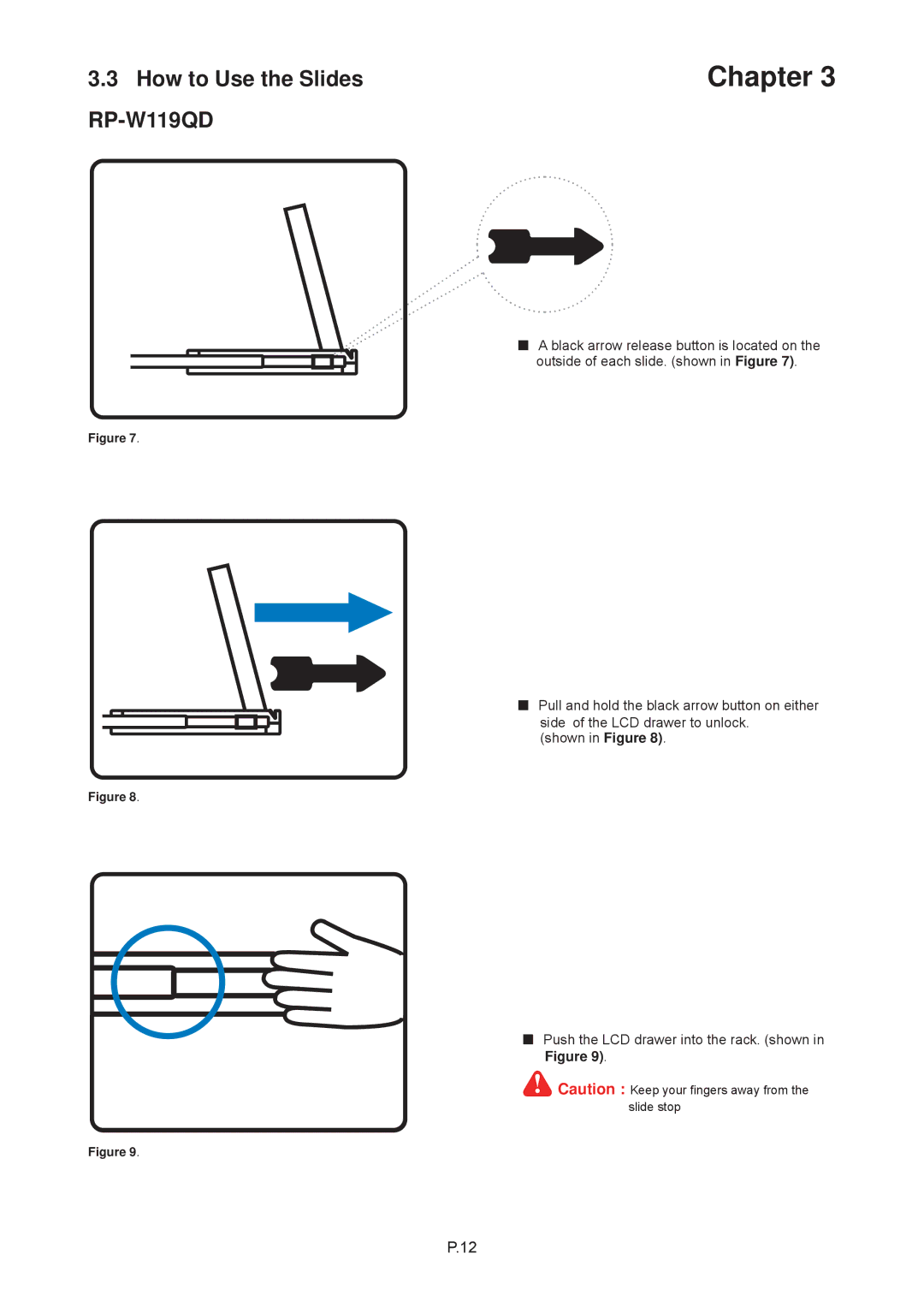
Contents Page RP-W119QD Part 2 43 LCD Quad Display RP-817QD, RP-919QD & RP-1020QD Blank Chapter Page Before Installation Combo DB-15 KVM Matrix Cat6 KVMMatrix DB-15 KVM Combo Cat6 KVMPackage Contents Structure Diagram RP-W819QD & RP-W922QD RP-W819QD RP-W922QD Connection RP-W819QD & RP-W922QD RP-W119QD LCD interchangeable module kit One Man Installation Slides Thumb ScrewHow to Use the Slides RP-W119QD Connection LCD Specifications RP-W922QD, RP-W819QD & RP-W119QD D x H RP-817QD, RP-919QD & RP-1020QD Structure Diagram RP-817QD, RP-919QD & RP-1020QD Installation RP-817QD, RP-919QD & RP-1020QD Connection RP-817QD, RP-919QD & RP-1020QD RP-117QD, RP-119QD & RP-120QD Structure Diagram RP-117QD, RP-119QD & RP-120QD How to Use the Slides RP-117QD, RP-119QD & RP-120QD Connection LCD Specifications RP117QD series D x H WeightMembrane For LCD OSD MenuOn-screen Menu Terminations Ch1 In, Ch2 In, Ch3 In, and Ch4 In Video in connectorsVCR VCR outVCR Connection for Tape Recording Start and Stop Control Alarm I/OVideo Loss Alarm Sensor Activated AlarmChapter 3 4 Pin assignment of the male type 9 pin D-sub connectorXX-DF Channel Select Byte Start Stop StartChapter Quad button #4 Channel Select buttons #5 Function Setup buttons #1, #2 Function CH Select buttons #5Quad Display Control Quad CH Select Function Button #2 Button #4 Button #5TIME/DATE setup 1 of the Setup Menu Display SettingTitle setup Dwell Time setupSave the settings and exit Setup Menu mode 2 of the setup menu- Alarm SettingAlarm Hold Duration Loss AlarmAuto-Sequence Mode Quad Display ModeFull Screen Display Mode Still Frame Display ModeVCR Operations Input rating Output ratingEfficiency Troubleshooting Blank