SBA-7222G-T2 Blade Module User’s Manual
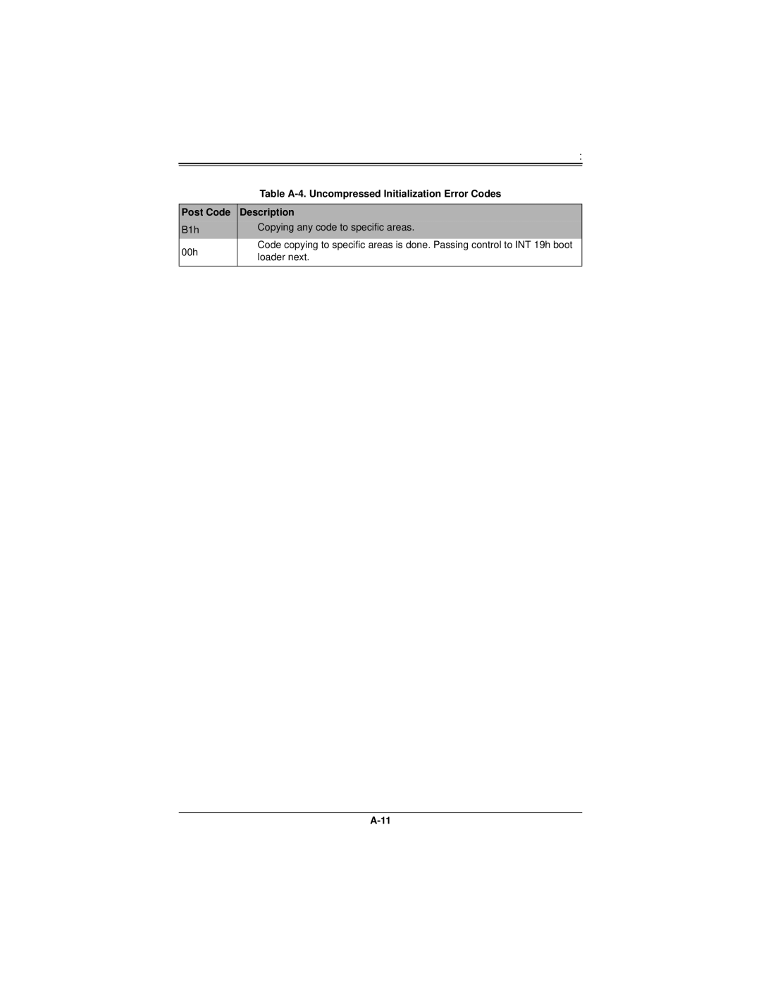
| Table | |
|
| |
Post Code | Description | |
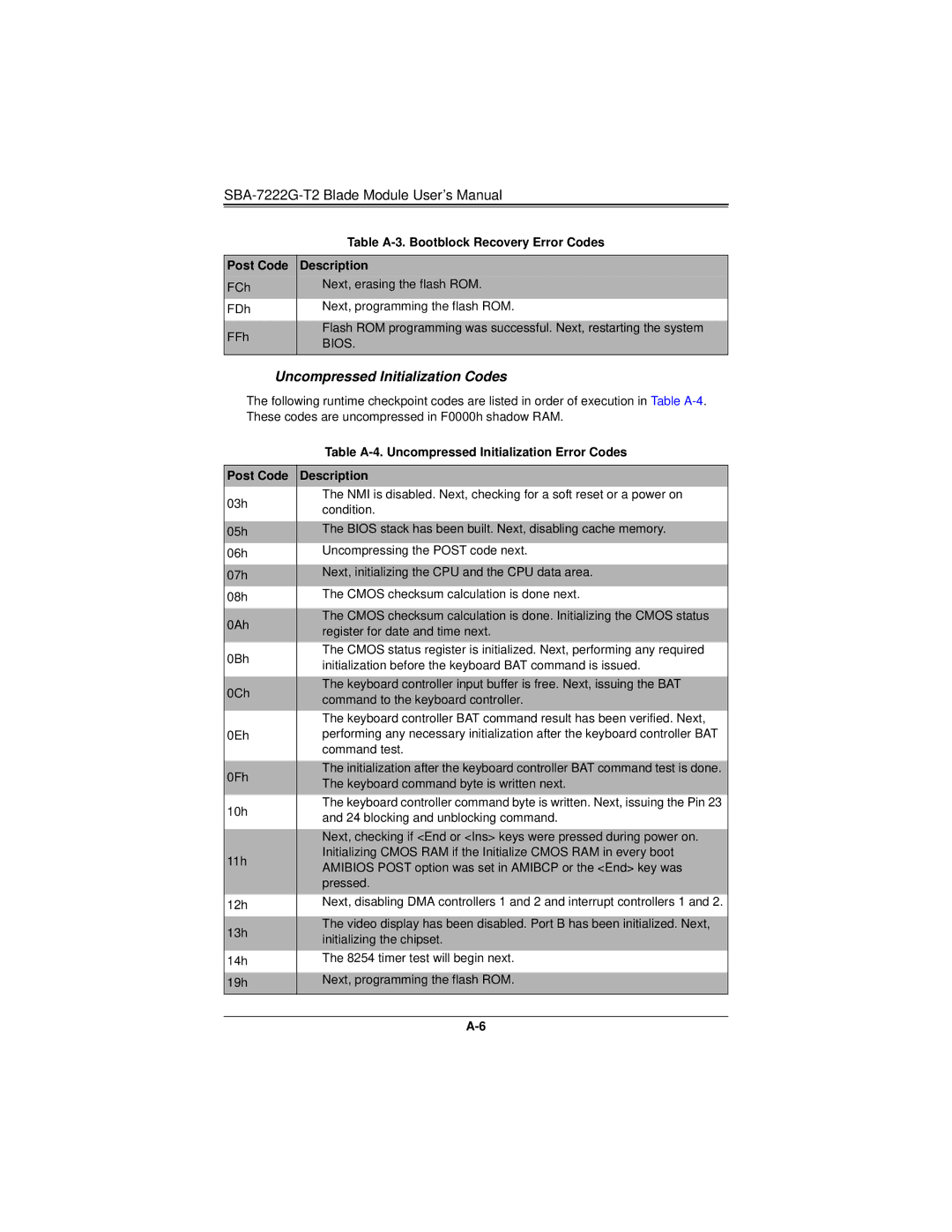
FCh | Next, erasing the flash ROM. | |
FDh | Next, programming the flash ROM. | |
|
| |
FFh | Flash ROM programming was successful. Next, restarting the system | |
BIOS. | ||
| ||
|
|
Uncompressed Initialization Codes
The following runtime checkpoint codes are listed in order of execution in Table
| Table | |
|
| |
Post Code | Description | |
03h | The NMI is disabled. Next, checking for a soft reset or a power on | |
condition. | ||
| ||
|
| |
05h | The BIOS stack has been built. Next, disabling cache memory. | |
06h | Uncompressing the POST code next. | |
|
| |
07h | Next, initializing the CPU and the CPU data area. | |
08h | The CMOS checksum calculation is done next. | |
|
| |
0Ah | The CMOS checksum calculation is done. Initializing the CMOS status | |
register for date and time next. | ||
| ||
0Bh | The CMOS status register is initialized. Next, performing any required | |
initialization before the keyboard BAT command is issued. | ||
| ||
|
| |
0Ch | The keyboard controller input buffer is free. Next, issuing the BAT | |
command to the keyboard controller. | ||
| ||
| The keyboard controller BAT command result has been verified. Next, | |
0Eh | performing any necessary initialization after the keyboard controller BAT | |
| command test. | |
|
| |
0Fh | The initialization after the keyboard controller BAT command test is done. | |
The keyboard command byte is written next. | ||
| ||
10h | The keyboard controller command byte is written. Next, issuing the Pin 23 | |
and 24 blocking and unblocking command. | ||
| ||
|
| |
| Next, checking if <End or <Ins> keys were pressed during power on. | |
11h | Initializing CMOS RAM if the Initialize CMOS RAM in every boot | |
AMIBIOS POST option was set in AMIBCP or the <End> key was | ||
| ||
| pressed. | |
12h | Next, disabling DMA controllers 1 and 2 and interrupt controllers 1 and 2. | |
|
| |
13h | The video display has been disabled. Port B has been initialized. Next, | |
initializing the chipset. | ||
| ||
14h | The 8254 timer test will begin next. | |
|
| |
19h | Next, programming the flash ROM. | |
|
|