VXI CT-100C Series Six-Slot VXIBus Chassis, 82-0102-000 CT-100C Specifications, Mtbf, Mttr

Page 17

www.vxitech.com

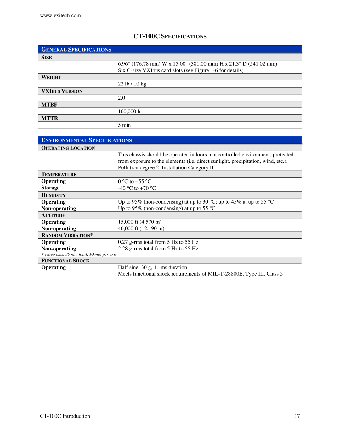
CT-100C SPECIFICATIONS

GENERAL SPECIFICATIONS

SIZE

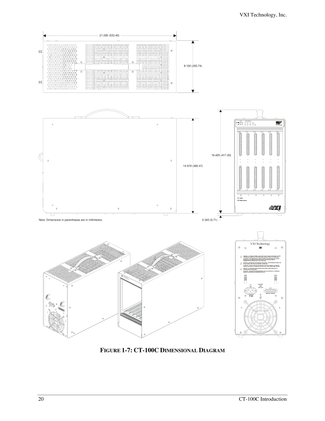
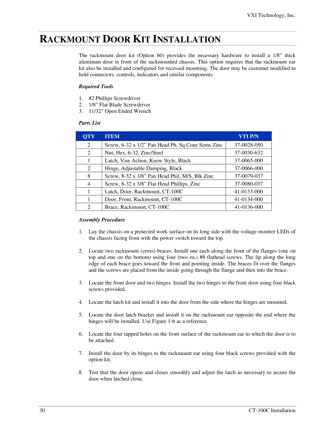
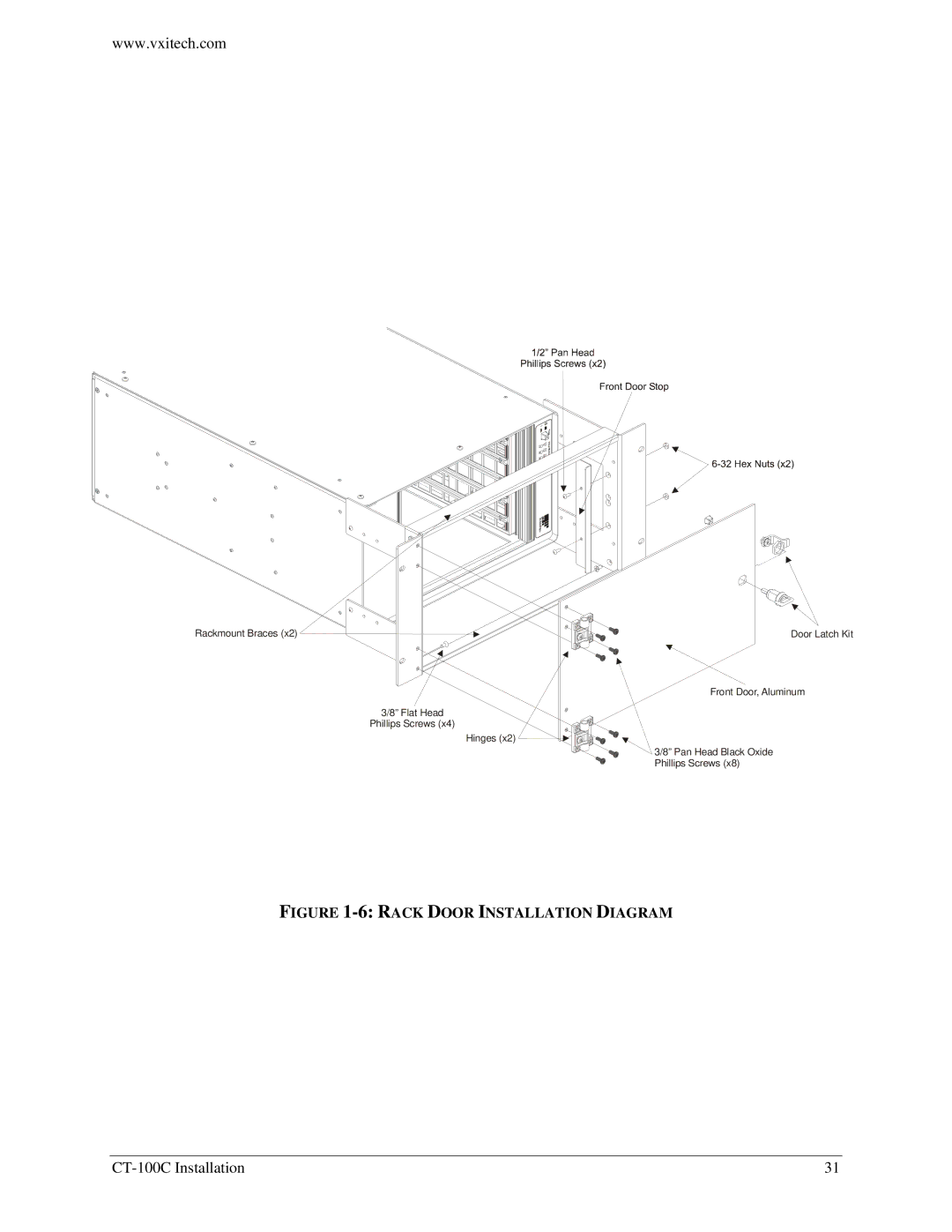
6.96" (176.78 mm) W x 15.00" (381.00 mm) H x 21.3" D (541.02 mm) Six C-size VXIbus card slots (see Figure 1-6for details)

WEIGHT

22 lb / 10 kg

VXIBUS VERSION

2.0

MTBF

100,000 hr

MTTR

5 min

ENVIRONMENTAL SPECIFICATIONS

OPERATING LOCATION


This chassis should be operated indoors in a controlled environment, protected


from exposure to the elements (i.e. direct sunlight, precipitation, wind, etc.).


Pollution degree 2. Installation Category II.

TEMPERATURE


Operating

0 °C to +55 °C

Storage

-40 °C to +70 °C

HUMIDITY


Operating

Up to 95% (non-condensing) at up to 30 °C; up to 45% at up to 55 °C

Non-operating

Up to 95% (non-condensing) at up to 55 °C

ALTITUDE


Operating

15,000 ft (4,570 m)

Non-operating

40,000 ft (12,190 m)

RANDOM VIBRATION*


Operating

0.27 g-rms total from 5 Hz to 55 Hz

Non-operating

2.28 g-rms total from 5 Hz to 55 Hz

* Three axis, 30 min total, 10 min per axis.


FUNCTIONAL SHOCK


Operating

Half sine, 30 g, 11 ms duration


Meets functional shock requirements of MIL-T-28800E, Type III, Class 5

CT-100C Introduction

17

Image 17
Contents CT-100C Series VXI Technology, Inc Table of Contents Limitation of Warranty WarrantyCertification Restricted Rights LegendEMC C L a R a T I O N O F C O N F O R M I T YTerms and Symbols General Safety InstructionsAvoid Electric Shock Support Resources CT-100C Preface Page Introduction IntroductionPerformance General DescriptionBackplane 2CT-100CSIX-SLOT Chassis Covers OFF FlexibilityMainframe Feature Locations CT-100C Mainframe FeaturesFront Panel Voltage Monitors Voltage Monitor LedsJ201 Connector PIN Detail J201 Connector PIN AssignmentsMttr CT-100C SpecificationsMtbf Input Voltage / Freq Fan atH igh Speed Fan at Low S peed 7CT-100C Dimensional Diagram Installation Remote POWER-ON Switch Wiring Remote POWER-ON Option+5 V Standby Usage +5 V Standby Wiring DiagramFAN Speed Switch Location FAN Speed SwitchOverview Rackmount Option InstallationParts List Rackmount KIT InstallationRackmount EAR Installation Diagram Assembly Instructions Rack Slide Installation 20Rack Slide Installation Diagram Rackmount Door KIT Installation Rack Door Installation Diagram Acrylic Rackmount Door KIT Installation Acrylic Rack Door Installation Diagram Installation Procedure Installation of VXI ModulesDisconnecting the Mainframe VXI Technology, Inc CT-100C Installation Replicable Parts List Service InformationCT-100C Power Supply Replacement Power Supply Replacement Diagram Cleaning the Mainframe Index