Promise Technology TX8, TX4 user manual Daisy Chaining Several UltraTrak100s Together

Page 12

UltraTrak100 TX4 and UltraTrak100 TX8 User Manual

(the one which is attached to the SCSI adapter) to the top connector, and place an LVD SCSI active terminator on the other connector. An LVD SCSI active terminator is included with UltraTrak100 disk array unit.

If the array is to be placed in the middle of a daisy-chained configuration, connect the incoming cable (the one which is attached to the SCSI adapter) to the top connector and connect the outgoing cable (the one which continues on to other devices) to the other connector. In this case, no terminator is required at the array, but the last device in the daisy chain must be terminated.

Correct SCSI termination procedures require that the first and last devices on the SCSI bus be terminated. If the first or last device is not terminated, or if devices other than the first and last are terminated, erratic SCSI bus performance will occur. Typically, the system or host adapter is the first device and is already terminated. When installing the UltraTrak100 disk array on a SCSI bus with other devices, make sure the above rules are observed with all devices on the SCSI bus. Consult your system and/or host adapter manual for additional information on correct termination procedure.

Caution

Improper system operation will occur if the SCSI termination is incorrect. Active termination and SCSI-3 compliant cables must be used. A SCSI-3 compliant cable is included with the UltraTrak100.

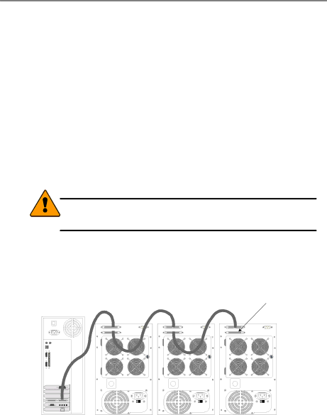
DAISY CHAINING MULTIPLE ARRAYS

Use a standard 68-pin SCSI-3 cable assembly to attach the array to the SCSI chain. Attach each cable to the individual units to be connected on the SCSI bus. Ensure that each device has a unique SCSI ID and that only the first and last devices are terminated.


Terminator

Computer or

UltraTrak100 TX4

UltraTrak100 TX4

UltraTrak100 TX4

Workstation


Figure 3. Daisy Chaining Several UltraTrak100s Together

DAISY CHAINING WITH OTHER SCSI DEVICES

This procedure is essentially the same as the procedure outlined above for multiple arrays. Refer to the manual associated with the other device or devices for additional information that may be pertinent to that unit. Ensure that each

6

Image 12
Contents ULTRATRAK100 TX4 ULTRATRAK100 TX8 Copyright TrademarksImportant Data Protection Information Radio Frequency Interference Statement Table of Contents RAID Page Introduction Architectural DescriptionFeatures and Benefits Feature BenefitInstall Hard Drives ConfigurationGetting Started Unpack ULTRATRAK100UltraTrak100 Disk Drive Access TX4 Shown Connecting the Scsi Cables Back of UltraTrak100 TX4 see for TX8Daisy Chaining Several UltraTrak100s Together Connect Power Cable and Switch Power on Assign a Scsi IDConfigure the ULTRATRAK100 Press SEL to Save Changes Choosing a RAID Level Advantages DisadvantagesCharacteristics/Advantages Disadvantages RAID 0+1Partition and Format the Array JbodMaintenance Drive Status IndicatorsIndicator Color Meaning Critical & Offline ArraysREBUILDING/SYNCHRONIZING Fault Tolerant Arrays When a Disk Drive FailsReplacing a Disk Drive Module Drive Replacement Drive CarrierConnecting Cables to Disk Drive Replacing a Power Supply Module TX8 onlyBack of UltraTrak100 TX8 ULTRATRAK100 Front Panel Interface Type of Interface Name CommentsError Mode Configuration ModeLCD Messages Array FunctionalView Status Configure Array Configure Cache Configure ScsiView Status View Controller Info View Cache StatsView Array Information View EnclosureView Controller Information Temperature 30C/86F Array 0 Size 12GBRAID 0 Functional 5009 RPMCreate/Cancel Auto Array Setup Press SEL to Create Press Exit to Cancel What you can doView Drive Assignments Define Array Delete ArrayNo Free Disk What you can do Maxtor Asng In Ary IBM Asng In AryRAID Level 4KB 8KB Maxtor Free IBM Assigned Maxtor FreeWipe out disk Synchronize Array Disable Buzzer Array ID Rebuild/Sync Pri. LowWrite Cache Write Cache What you can doWrite Back Write Thru What you can do Write BackMode ID SelectedScsi ID Press Or to move these items on the LCD What you can doTechnical Support Services Contacting Promise SupportUSA Tech Support Center European Tech SupportPacific Rim Sales Office China OfficeLimited Warranty Disclaimer of Other WarrantiesPage Returning Product for Repair USA & Canada Your Responsibilities Appendix a Technology Background Introduction to RAIDRAID 1 Mirroring RAID 0+1 STRIPING/MIRROR RAID 3 Block Striping with Parity Drive RAID 5 Block and Parity Striping Jbod Spanning Appendix B Frequently Asked Questions Why can’t I see the drives on the UltraTrak100 under FDISK?