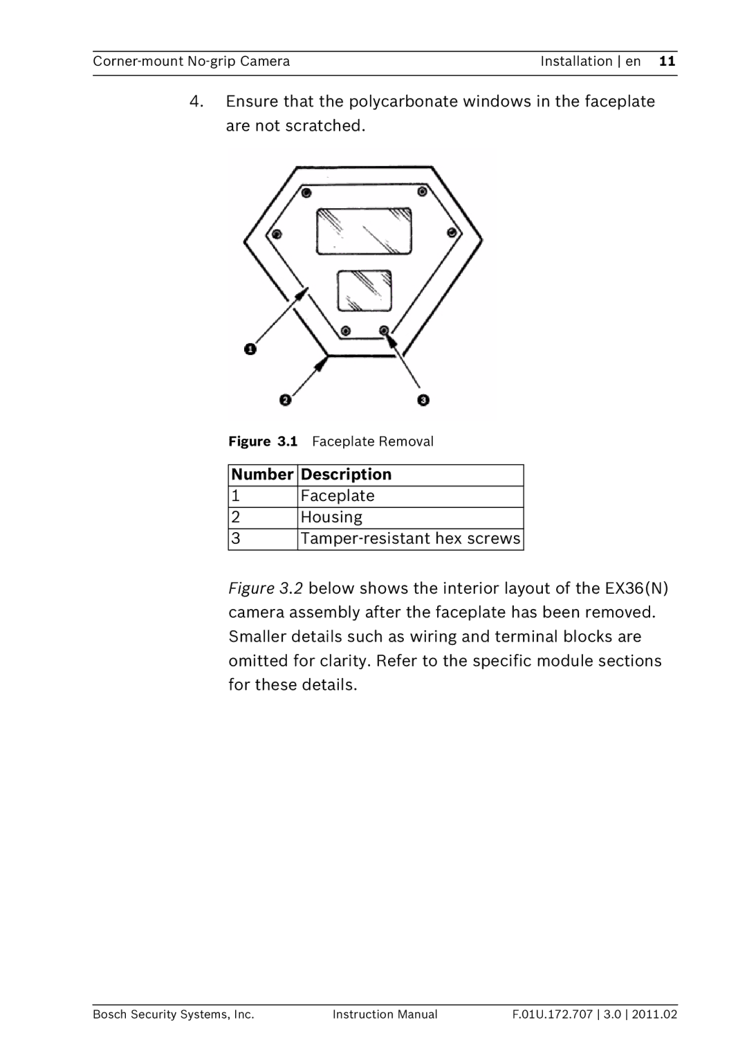
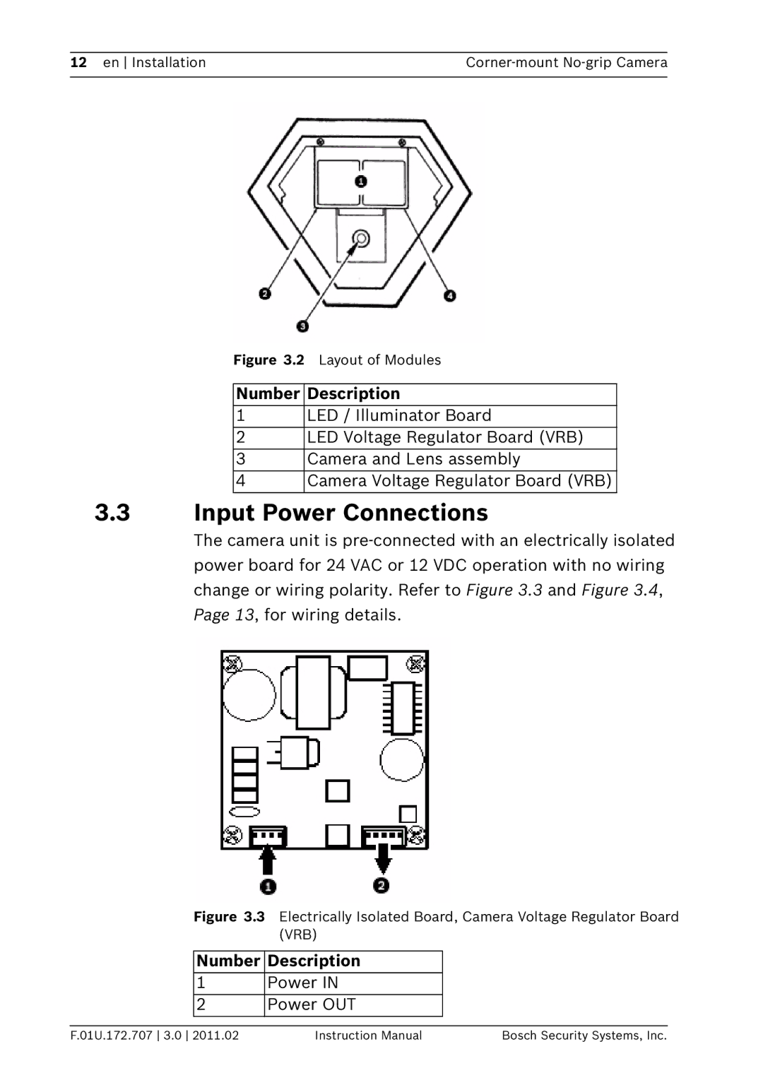
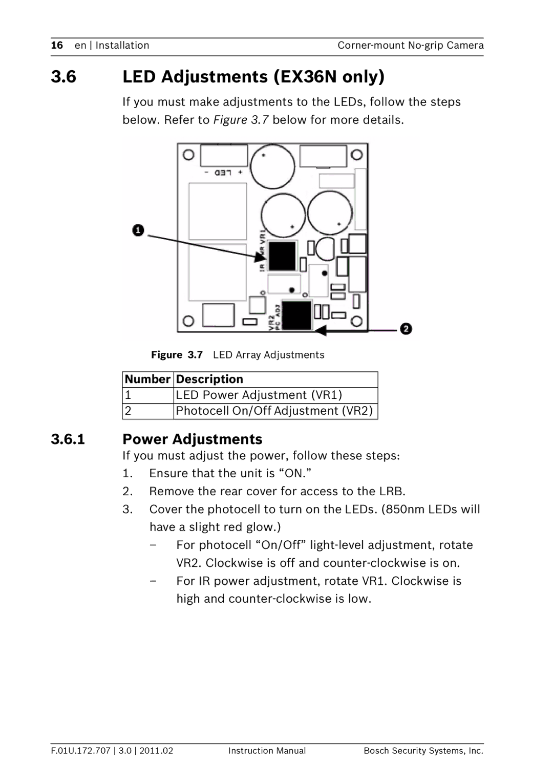
Bosch Appliances EX36N instruction manual Camera Re-assembly, Photocell Foam pad

Page 18

18 en Installation

Corner-mount No-grip Camera


3.8Camera Re-assembly

1.Ensure that all wires are properly connected, that all holes are sealed against moisture penetration, and that all mounting screws are tight.

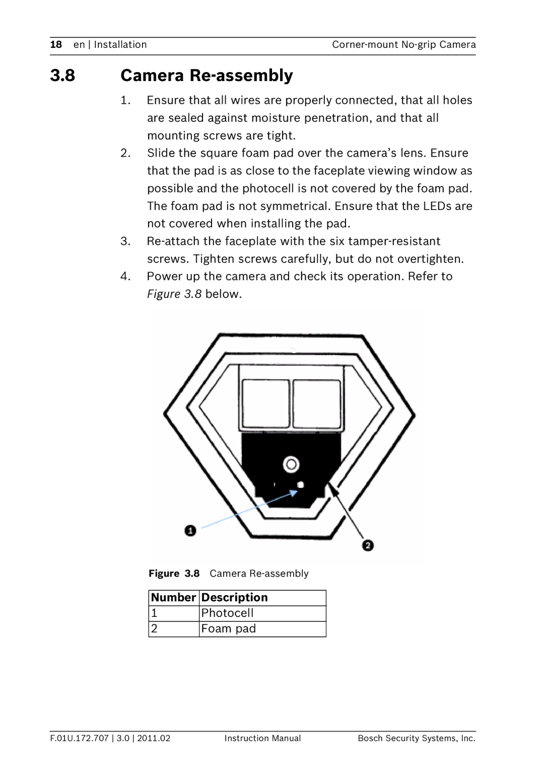
2.Slide the square foam pad over the camera’s lens. Ensure that the pad is as close to the faceplate viewing window as possible and the photocell is not covered by the foam pad. The foam pad is not symmetrical. Ensure that the LEDs are not covered when installing the pad.

3.Re-attach the faceplate with the six tamper-resistant screws. Tighten screws carefully, but do not overtighten.

4.Power up the camera and check its operation. Refer to Figure 3.8 below.

Figure 3.8 Camera Re-assembly

Number Description

1Photocell

2 Foam pad

F.01U.172.707 3.0 2011.02

Instruction Manual

Bosch Security Systems, Inc.

Image 18
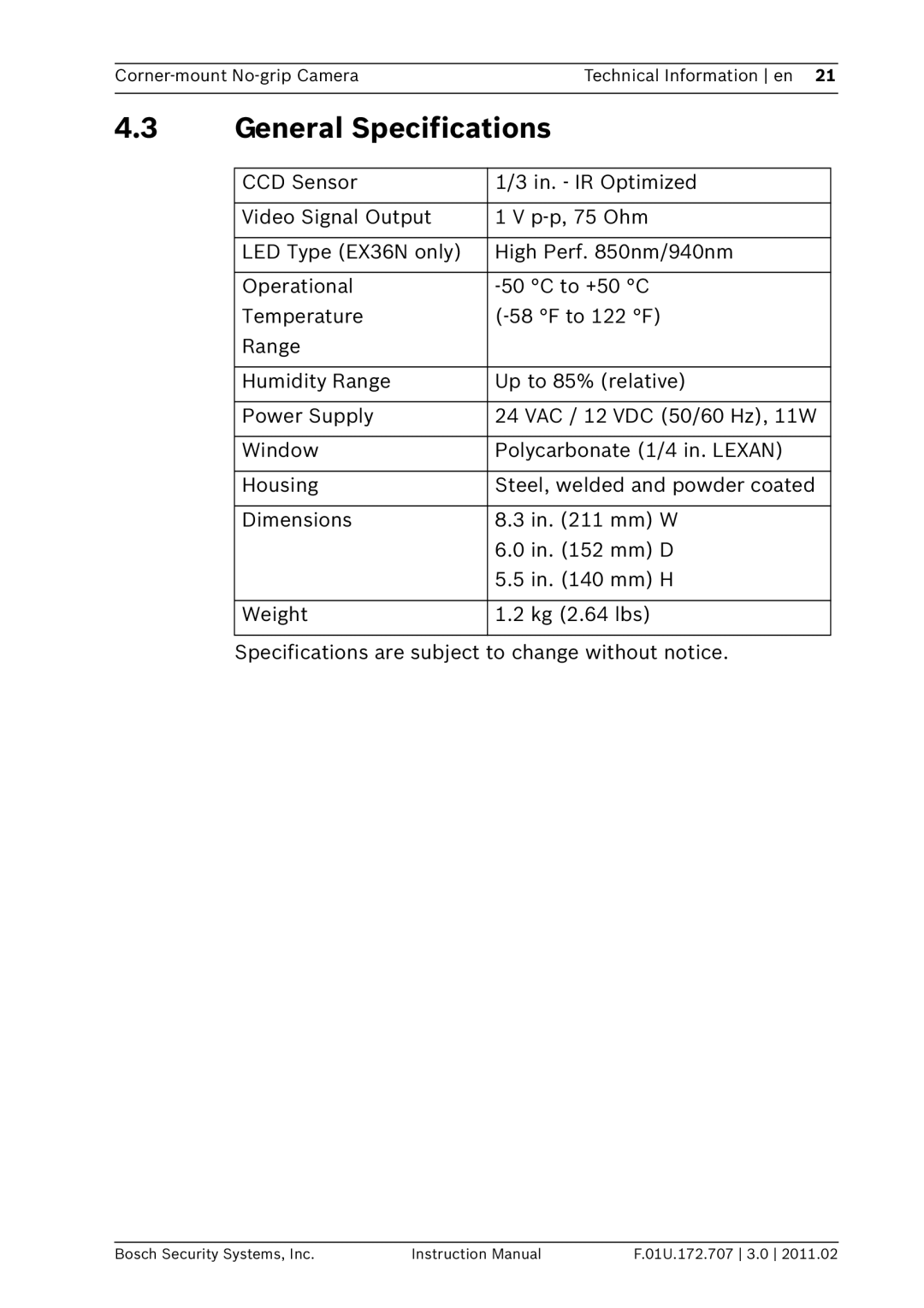
Contents EX36 Corner-mount No-grip Camera Page Table of Contents Safety Important Safety InstructionsCorner-mount No-grip Camera Safety en FCC Information Bosch Contact Information Parts List DescriptionUnpacking User-Supplied Parts Initial Preparations InstallationInstallation Step Faceplate RemovalNumber Description Faceplate RemovalInput Power Connections Layout of ModulesMounting the Camera Housing Board Connections, LED Voltage Regulator Board VRBMounting Holes EX36N Camera Housing Camera Directional Adjustment LED Adjustments EX36N only Power AdjustmentsLens Replacement Camera Re-assembly Photocell Foam padTroubleshooting Camera Technical InformationTroubleshooting LEDs Problem Possible SolutionGeneral Specifications En Technical Information Corner-mount No-grip Camera Page Bosch Security Systems, Inc