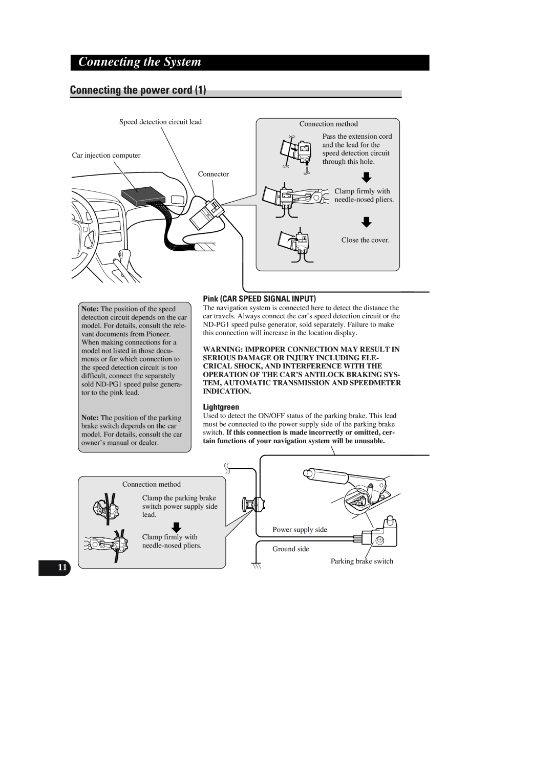
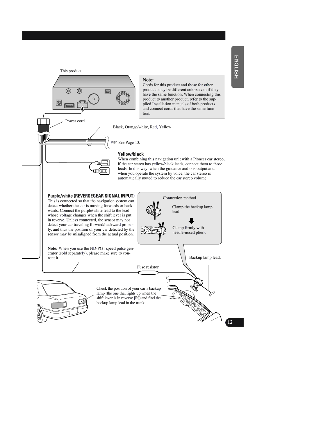
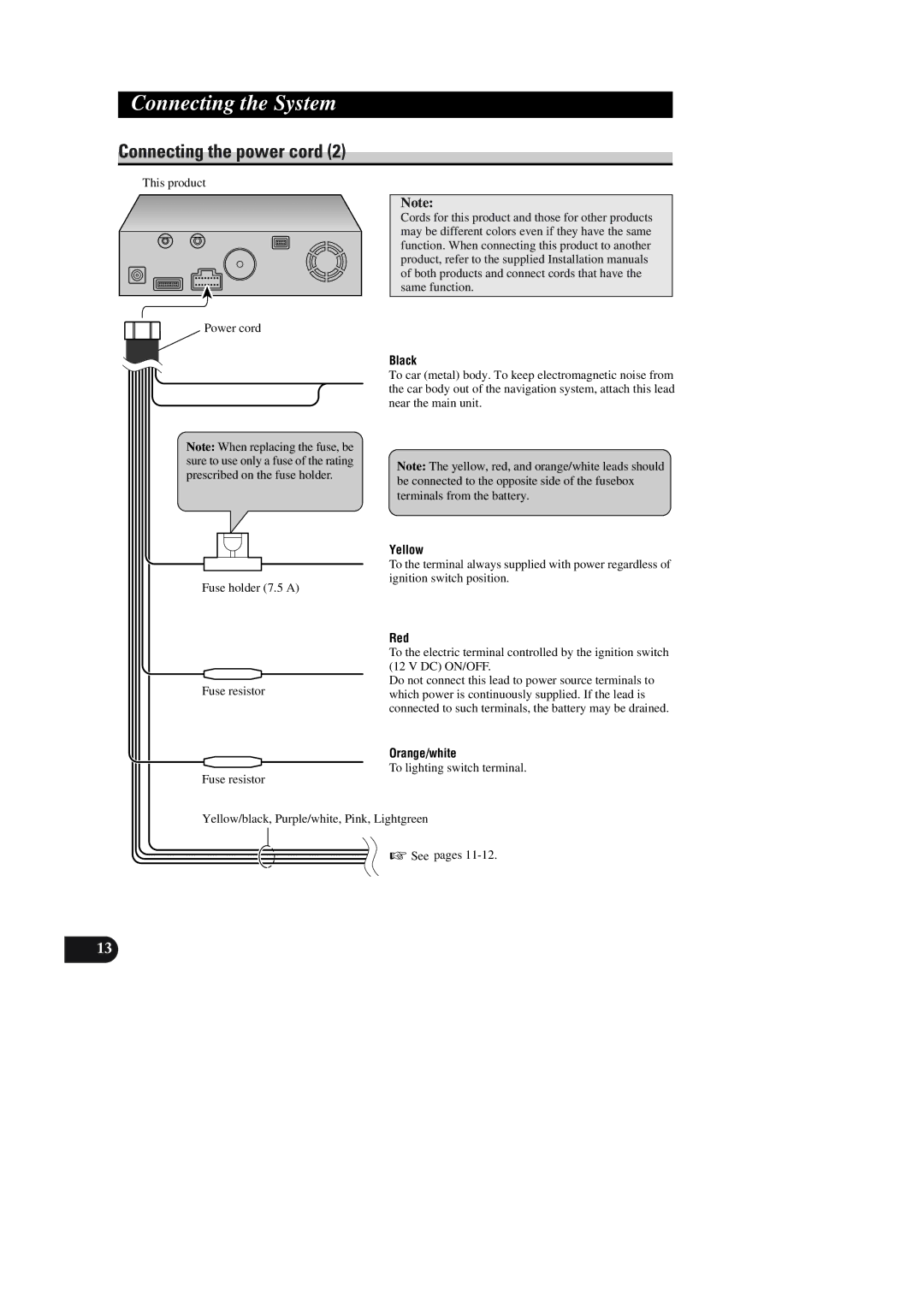
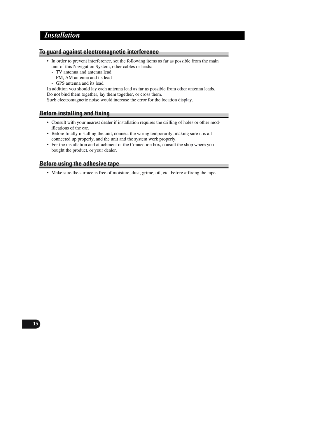
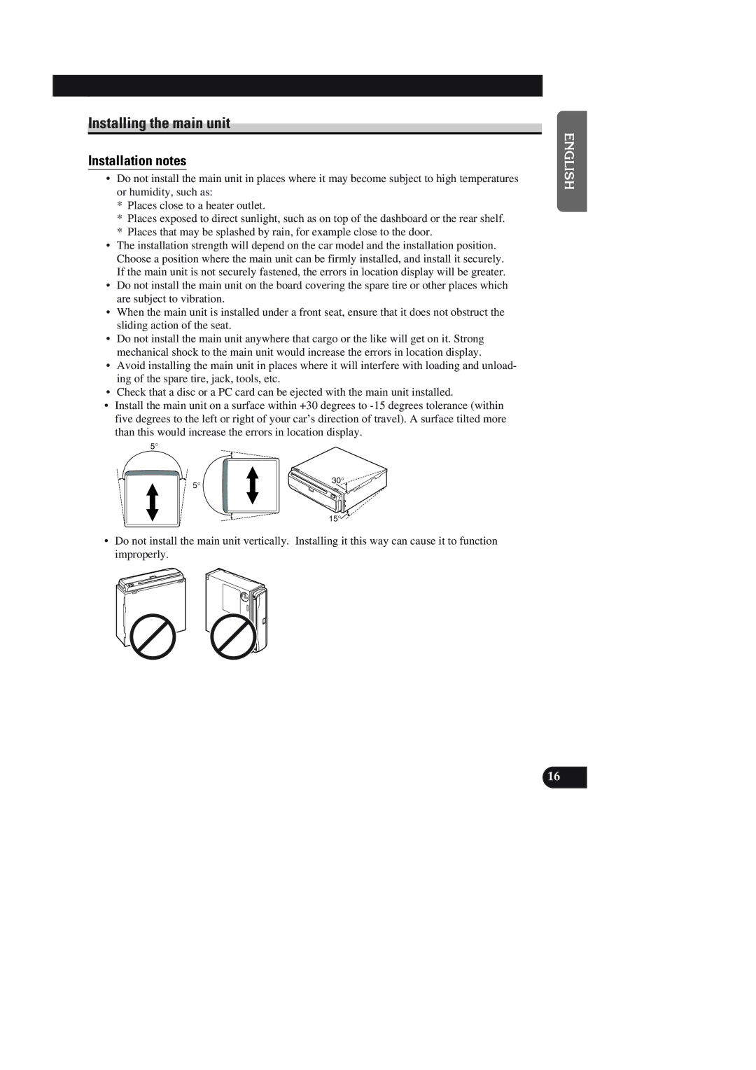
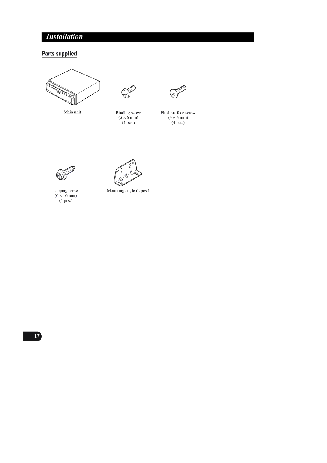
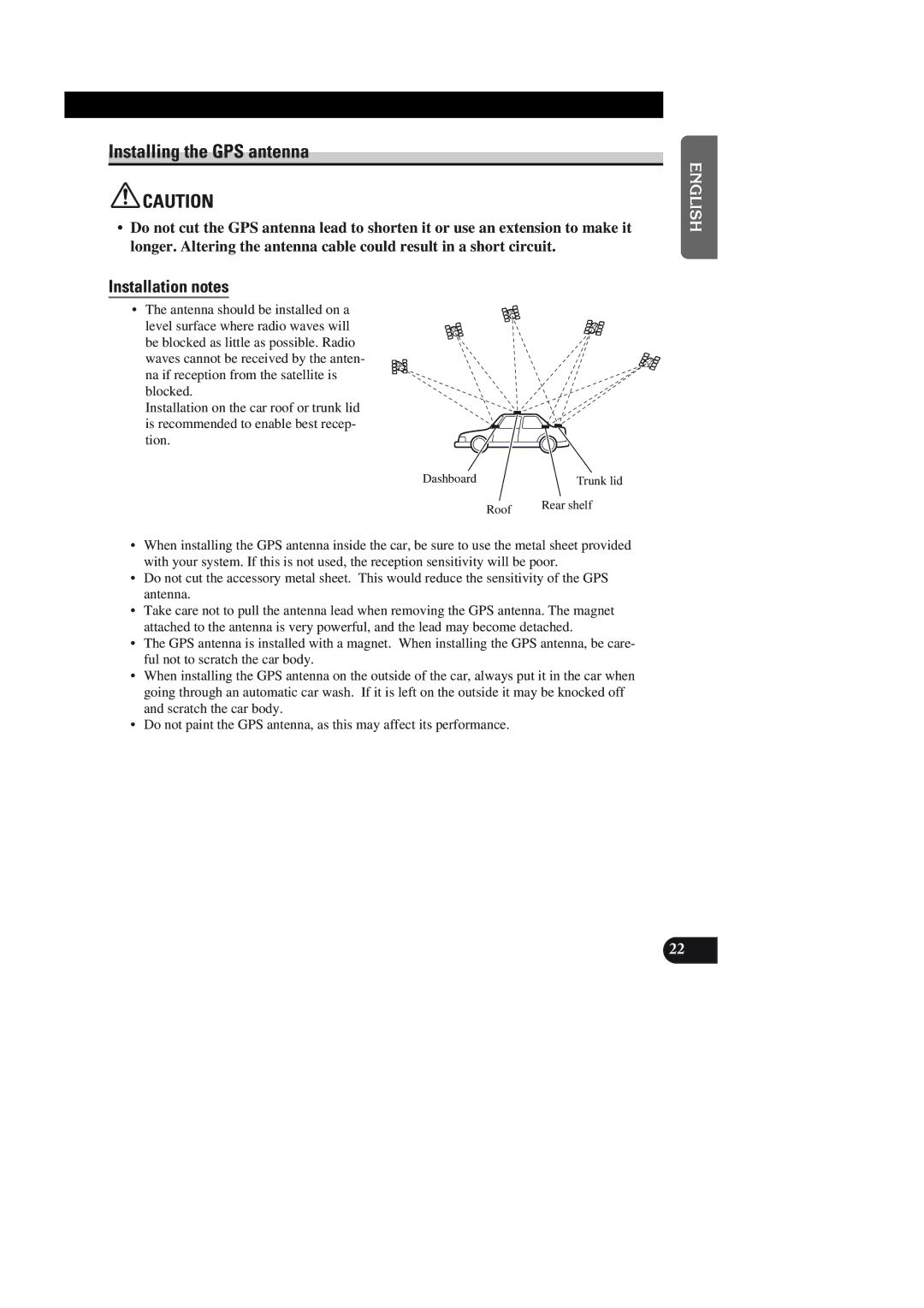
Pioneer AVIC-90DVD installation manual Locking screw, Installation direction lever

Page 19

CAUTION

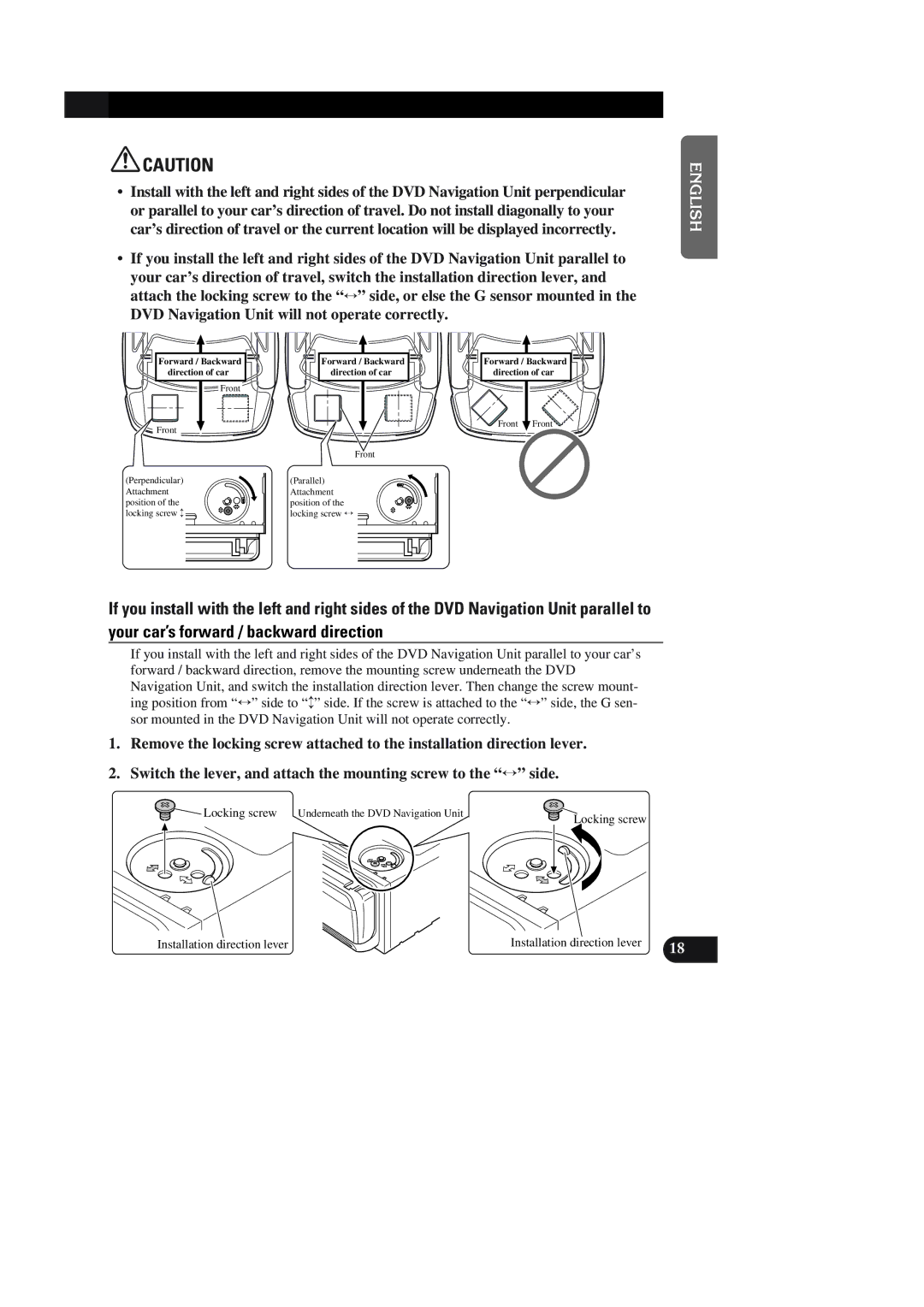
Install with the left and right sides of the DVD Navigation Unit perpendicular or parallel to your car’s direction of travel. Do not install diagonally to your car’s direction of travel or the current location will be displayed incorrectly.

If you install the left and right sides of the DVD Navigation Unit parallel to your car’s direction of travel, switch the installation direction lever, and attach the locking screw to the “” side, or else the G sensor mounted in the

DVD Navigation Unit will not operate correctly.

ENGLISH ESPAÑOL

Forward / Backward direction of car

Front

Front

(Perpendicular) Attachment position of the locking screw

Forward / Backward direction of car

Front

(Parallel) Attachment position of the locking screw

Forward / Backward direction of car

Front Front

DEUTSCH FRANÇAIS

If you install with the left and right sides of the DVD Navigation Unit parallel to your car’s forward / backward direction

If you install with the left and right sides of the DVD Navigation Unit parallel to your car’s forward / backward direction, remove the mounting screw underneath the DVD Navigation Unit, and switch the installation direction lever. Then change the screw mount- ing position from “” side to “” side. If the screw is attached to the “” side, the G sen- sor mounted in the DVD Navigation Unit will not operate correctly.

1.Remove the locking screw attached to the installation direction lever.

2.Switch the lever, and attach the mounting screw to the “” side.

Locking screw Underneath the DVD Navigation Unit

Locking screw

ITALIANO NEDERLANDS

Installation direction lever

Installation direction lever

18


Image 19
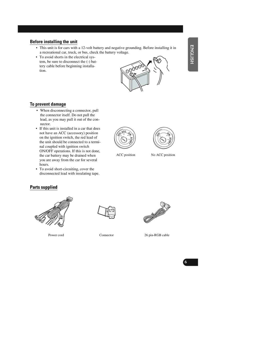
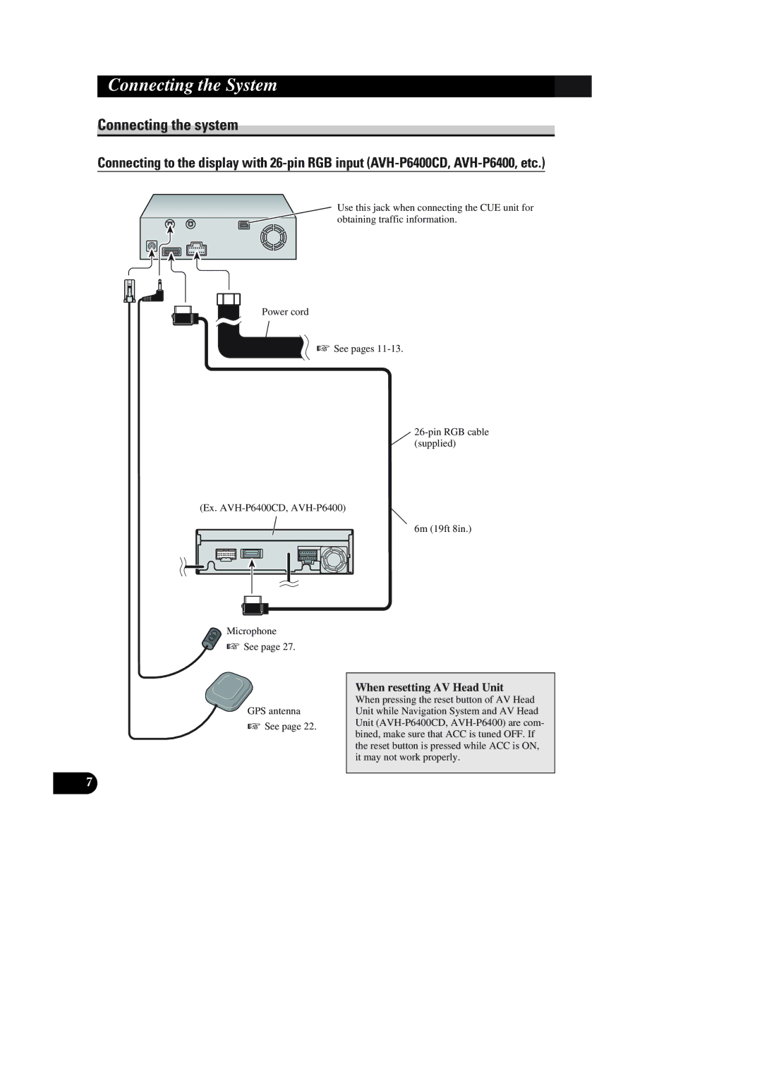
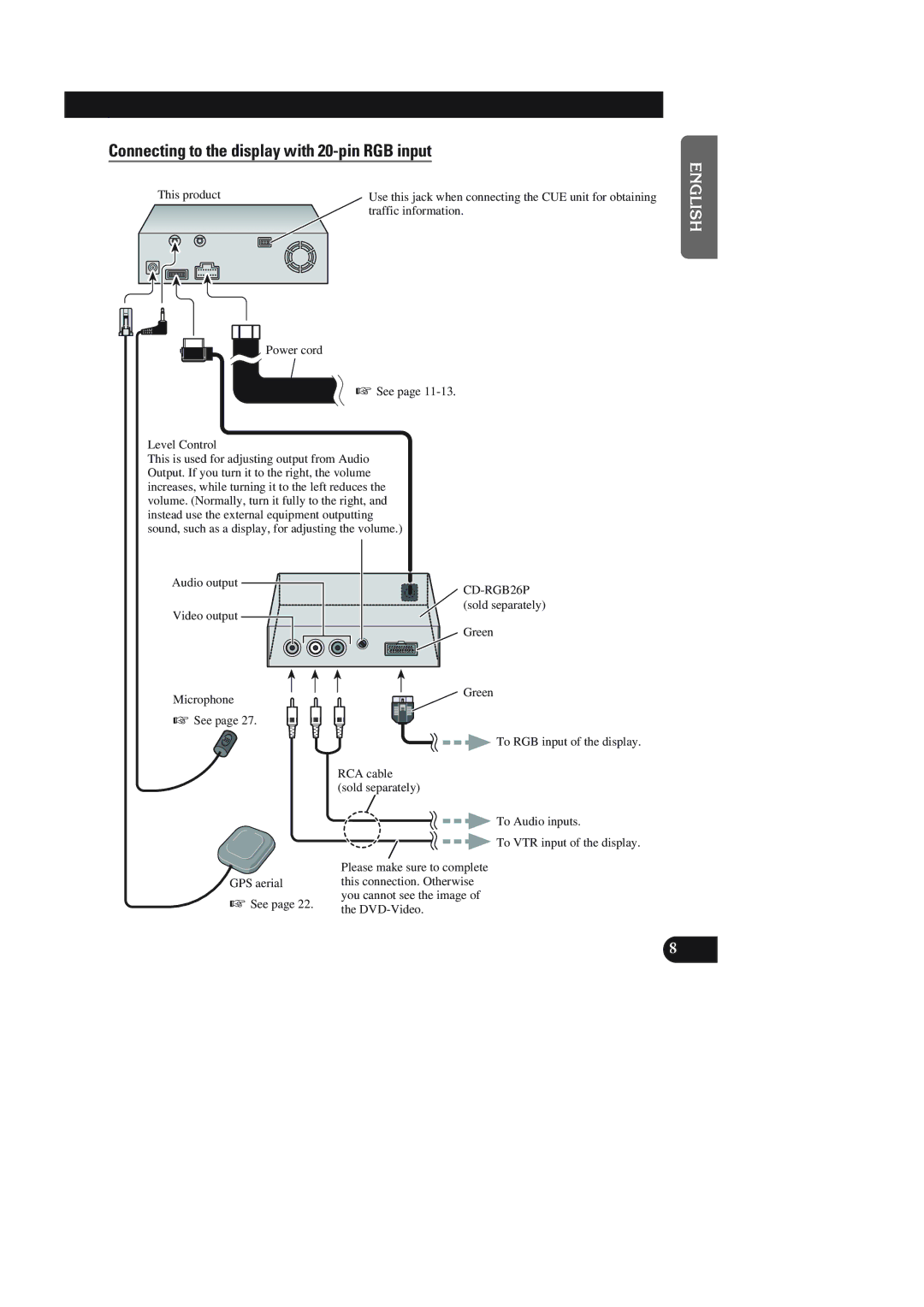
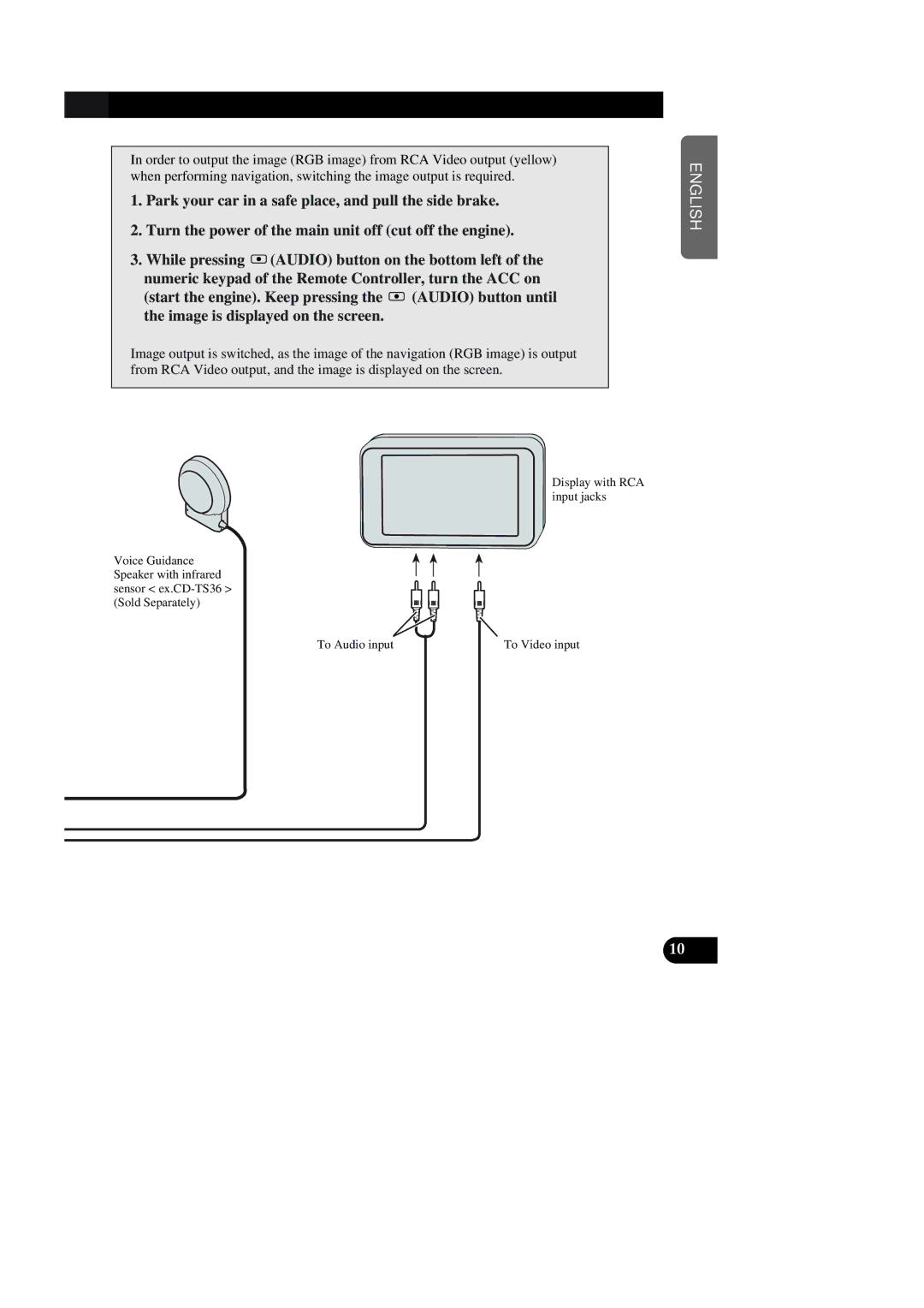
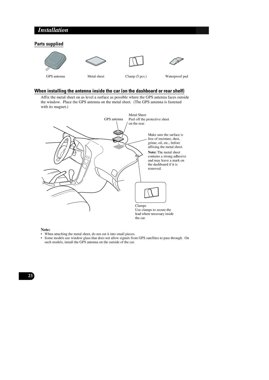
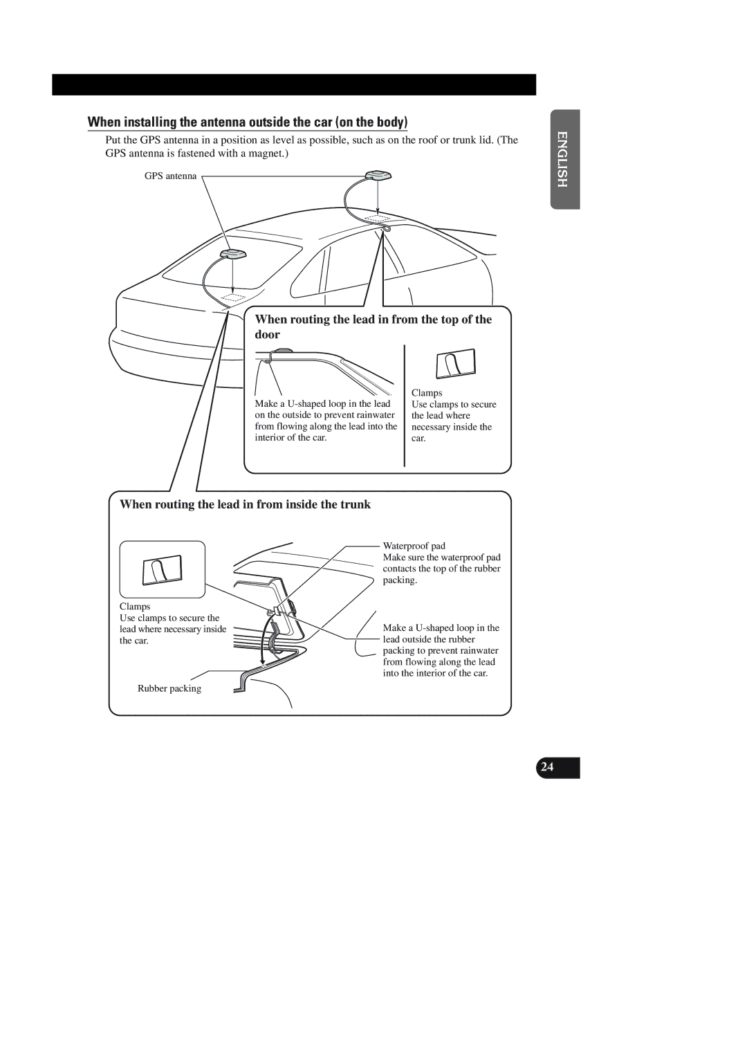
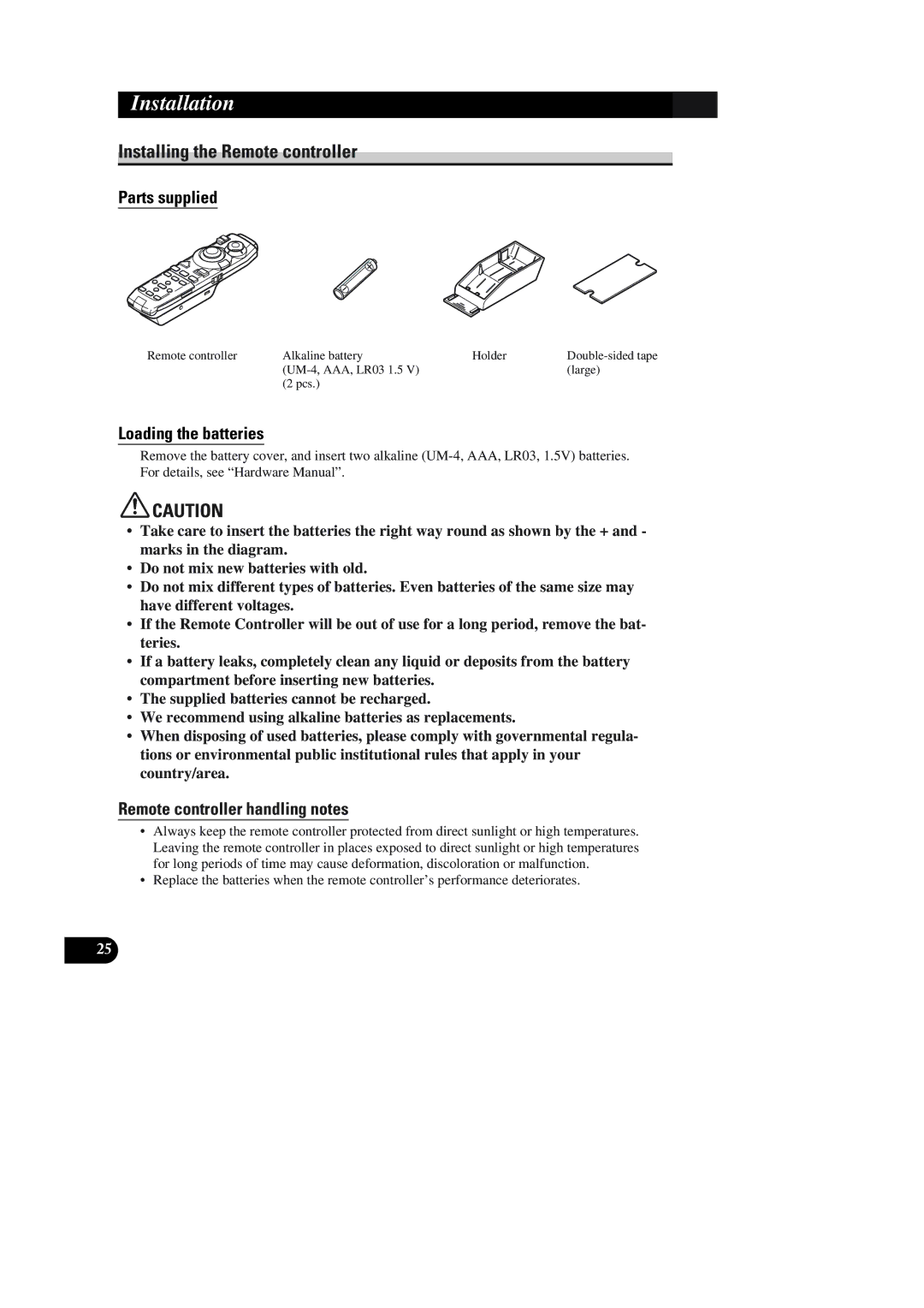
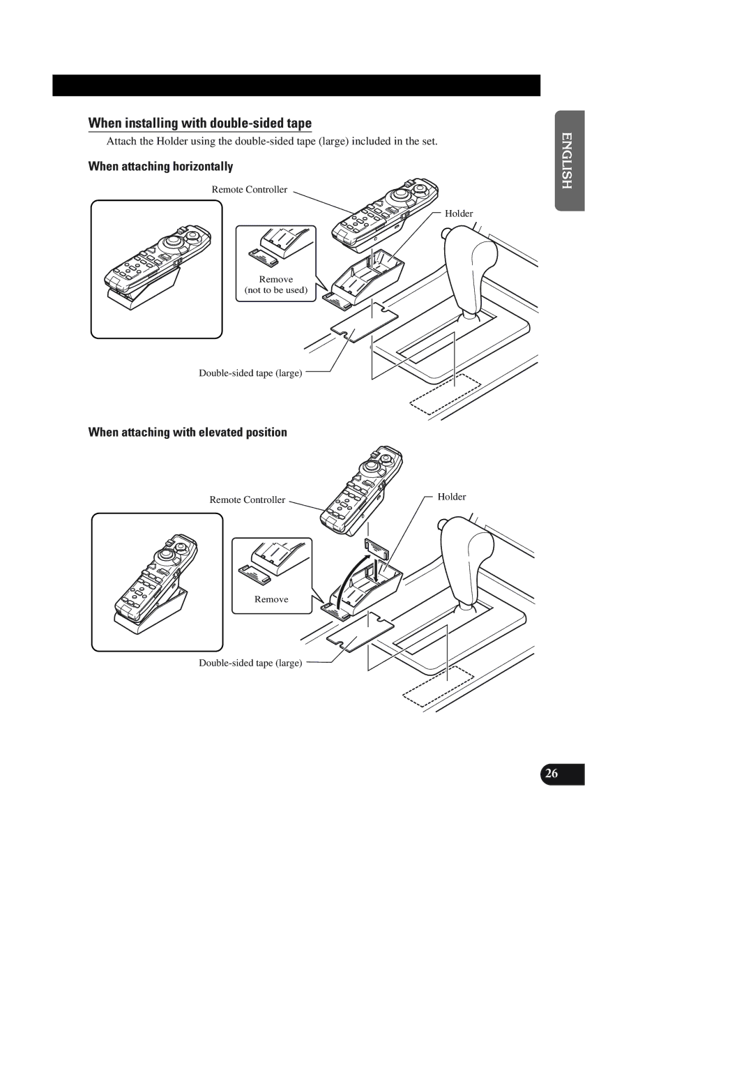
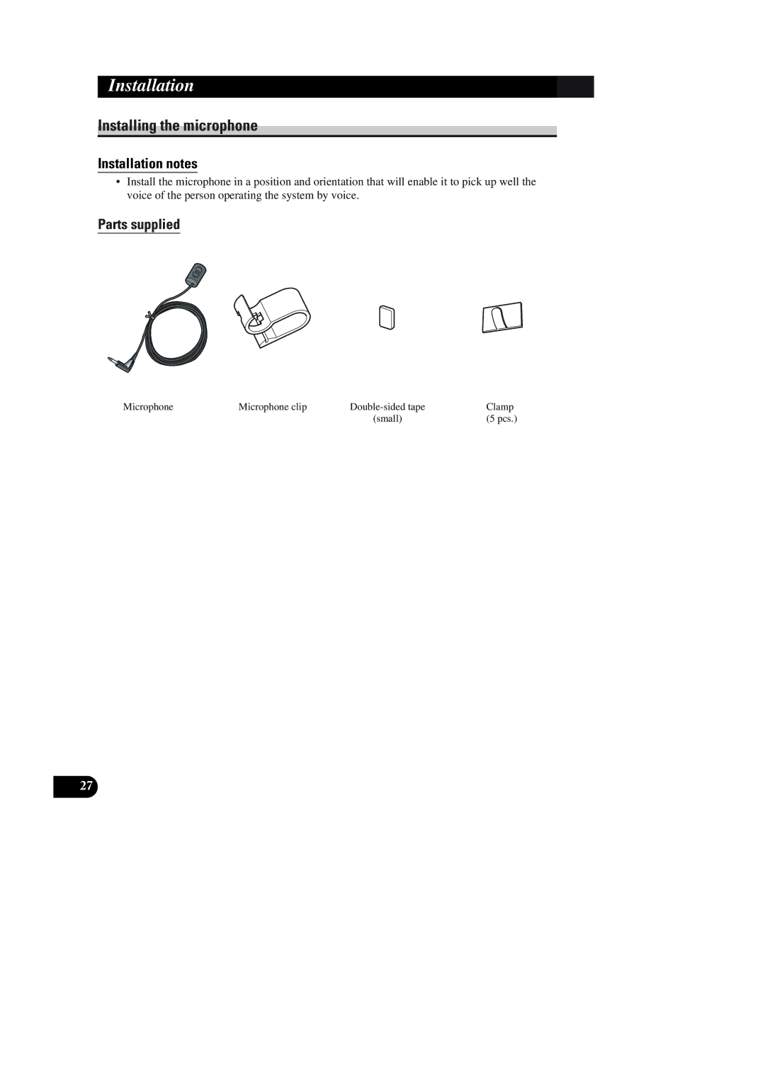
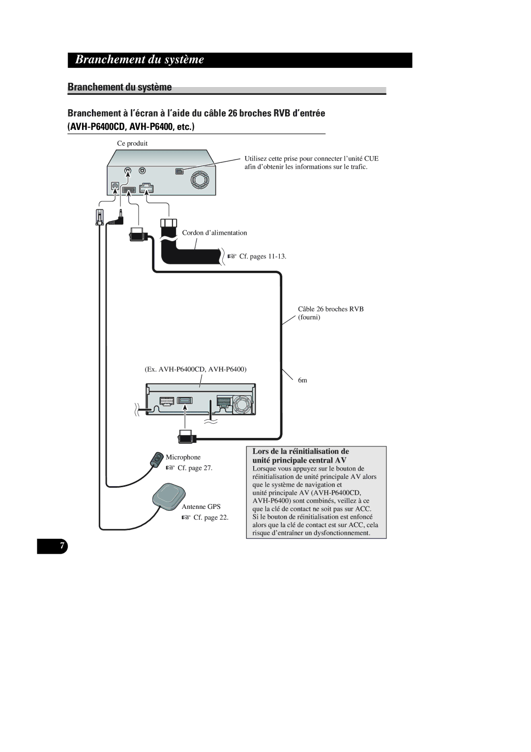
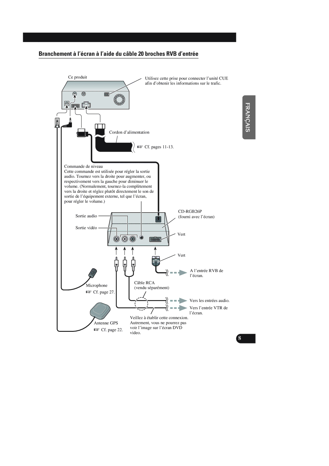
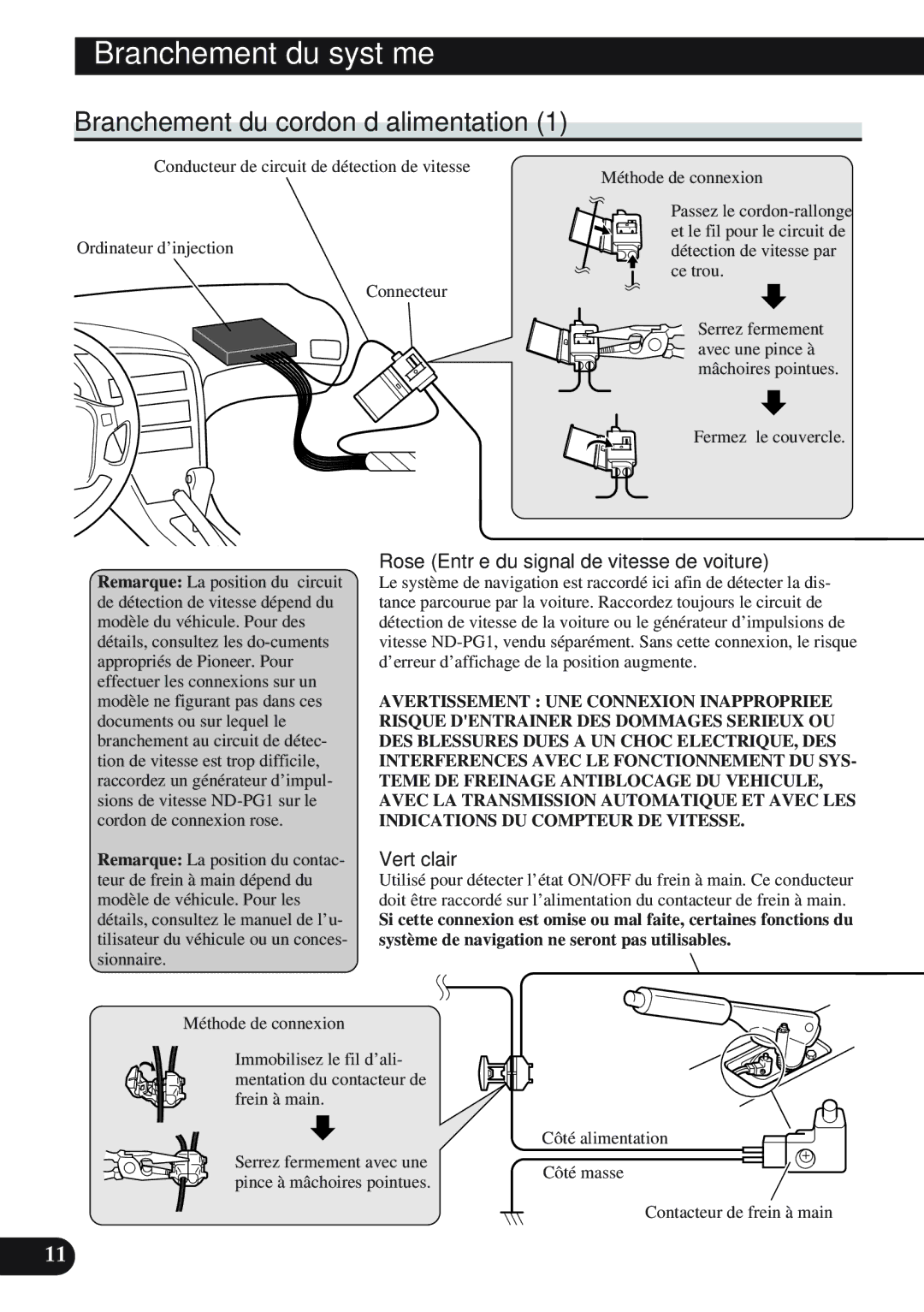
Contents Installation Manual Important Information Contents Important Safeguards English Español Deutsch Français Italiano Nederlands Connecting the System Parts supplied Before installing the unitPower cord Connector To prevent damageWhen resetting AV Head Unit Connecting the systemConnecting to the display with 20-pin RGB input Connecting the System To Video input Needle-nosed pliers Ground side Parking brake switch Connecting the power cordClamp firmly with needle-nosed pliers Close the cover Fuse resistor Backup lamp lead in the trunkThis is connected so that the navigation system can Nect itYellow Installation Before using the adhesive tape Before installing and fixingTo guard against electromagnetic interference Installation notes Installing the main unitMain unit Locking screw Installation direction leverFit mounting angles to the sides of the main unit Floor Tapping screw Fix to the floor with tapping screwsFastening the unit to the factory radio mounting bracket Dashboard Installing the GPS antennaRoof Rear shelf GPS antenna Metal sheet Clamp 5 pcs Make a U-shaped loop in the lead Clamps When installing the antenna outside the car on the bodyWhen routing the lead in from the top of the door When routing the lead in from inside the trunkLoading the batteries Installing the Remote controllerRemote controller handling notes Remote controller Alkaline battery HolderDouble-sided tape large When installing with double-sided tapeRemote Controller Holder Remote ControllerMicrophone Microphone clip Installing the microphoneClamp Install the microphone on the microphone clip When installing the microphone on the sun visorInstall the microphone clip on the sun visor Install the microphone clip on the steering column When installing the microphone on the steering columnSet the navigation system Reconnecting the batteryStart the engine Press the reset button on the main unit Reset buttonInformation Importante Branchement du système dans le cas d’un Remarques sur l’installation Pièces fourniesPour protéger le système de navigation Importantes Mesures DE Securite English Français Deutsch Français Italiano Nederlands Branchement du système Position ACC Pas de position ACC Avant de raccorder l’appareilPour éviter des dégâts Pièces fourniesCe produit Branchement du systèmeSortie vidéo Cordon d’alimentation Cf. pages Commande de niveauAfin d’obtenir les informations sur le trafic Sortie audioVert Microphone Cf. Câble RCA vendu séparément Antenne GPS Sortie audio Sortie vidéoÉcran muni de prises d’entrée Cinch RCA Fermez le couvercle Branchement du cordon d’alimentationTion de chaque câble Les câbles de ce produit et ceux d’autresMême couleur bien que remplissant la Tion de chacun et effectuez les raccordeJaune Installation Avant d’employer le ruban adhésif Avant un branchement définitifRemarques sur l’installation Installation de l’unité principaleUnité principale Vis de verrouillage Sous l’unité de navigation DVD Levier du sens d’installationRouillage Installation Vis taraudeuse Plancher Fixez l’unité sur le plancher avec les vis taraudeusesDe diamètre Installation Planche de bord Toit Capot du coffre Lunette arrière Installation de l’antenne GPSAntenne GPS Plaque métallique Serre-fils 5 pièces Cheminement du fil par l’intérieur du coffre Cheminement du câble sur le haut de la portièreInsertion des piles Installation de la télécommandeRemarques sur le maniement de la télécommande Télécommande Pile alcaline SupportBoîtier de télécommande En cas dinstallation avec bande adhésive double faceRetirer Bande adhésive double face large Installation du microphone Microphone Attache Installation du microphone sur le pare-soleilFixez le microphone sur l’attache fournie Fixez l’attache du microphone sur le pare-soleilFixez l’attache du microphone sur la colonne de direction Installation du microphone sur la colonne de directionBande adhésive double face Branchement de la batterie Configurez le système de navigation automobileTouche de réinitialisation Page Page Pioneer Corporation
Related manuals
Manual 82 pages 34.94 Kb